Recording method of optical disk, optical disk recording apparatus, optical disk reproducing apparatus and optical disk

a recording method and optical disk technology, applied in the field of recording methods of optical disks, optical disk recording apparatuses, optical disk reproducing apparatuses and optical disks, can solve problems such as deterioration, higher data error ratios at the edge of data fields, and errors that tend to occur in reproduced data. to achieve the effect of reducing the occurrence of incorrect errors

Inactive Publication Date: 2006-06-13
SHARP KK
View PDF17 Cites 3 Cited by
  • Summary
  • Abstract
  • Description
  • Claims
  • Application Information

AI Technical Summary

Benefits of technology

[0017]The objective of the present invention is to provide a recording method for an optical disk which can reduce the occurrence of an incorrectable error in an optical disk in which areas formed as concave and convex sections on the disk substrate are arranged along a track with constant intervals, and also to provide an optical disk recording apparatus, an optical disk reproducing apparatus and an optical disk used in such a method.
[0020]Thus, in the recording area formed by the concave and convex areas on the optical disk substrate, data and parity placed adjacent to the concave and convex areas are dispersed. Therefore, even when an optical disk and an optical disk recording and reproducing device which might have a high error rate at the ends of a recording area adjacent to the concave and convex areas are used, the application of the error-correction decoding process at the time of playback makes it highly possible that the error correction is made, thereby improving the reliability in recording data.
[0023]With this arrangement, no data to be recorded is located on the ends of the recording area adjacent to the concave and convex areas of an optical disk substrate. Therefore, even when an optical disk which might have a high error rate at the ends of a recording area adjacent to the concave and convex areas is used and an optical disk recording and reproducing apparatus has a failure in correcting an error, it is possible to reduce an error occurring in important data sent from the host apparatus.

Problems solved by technology

In an optical disk, an error tends to occur in reproduced data due to a defect in a disk substrate or recording layer and dust and scratches on the surface of a disk substrate.
In particular, in recent years, since the recording density has become higher and since the thickness of the disk substrate has become as thin as 0.6 mm, the above-mentioned defect, dust, scratches, etc. are more likely to cause an error.
In particular, in the case of magneto-optical disks in which the control for birefringence of the disk substrate is essential, the edge of each data field in the track scanning direction tends to deteriorate in optical properties as compared with the other portion of the data field, resulting in a possible higher data error ratio at the edge of the data field.
For this reason, in a circuit process for converting a reproduced analog signal to a digital signal, deviations tend to occur in the process related to the edge portions of the data fields as compared with processes for the other portions of the data fields, resulting in a high error rate at the ends of the data fields.
In this case, when data that are to be recorded on the above-mentioned portions (ends of the data fields) adjacent to the servo fields are concentrated, for example, on the same column in the two-dimensional array in FIG. 8, the first encoding process in the error-correction encoding operation forms a code system on each column in the two-dimensional array; therefore, in the columns on the data field edge portions on which data are concentrated, there is a higher possibility of failure in correction in the decoding process of the error-correcting operation, as compared with the coding system of the first encoding process on the other columns.
Moreover, for the reason as described above, if there is an incorrectable error remaining in a column on which data (user data) are recorded as shown in FIG. 8, it is highly possible that the error causes malfunction in the host apparatus for processing reproduced data from the optical disk recording and reproducing apparatus.
In this manner, in the conventional optical recording method and optical disk recording and reproducing apparatus, in the case when an optical disk that might have a high data error rate particularly in the field ends is reproduced in an optical disk recording and reproducing apparatus, there is a higher possibility of failure in correction in the decoding process of the error-correcting operation and the resulting possibility of malfunction in the host apparatus.

Method used


Image

  • Recording method of optical disk, optical disk recording apparatus, optical disk reproducing apparatus and optical disk
  • Recording method of optical disk, optical disk recording apparatus, optical disk reproducing apparatus and optical disk
  • Recording method of optical disk, optical disk recording apparatus, optical disk reproducing apparatus and optical disk

Examples


embodiment 1

[Embodiment 1]

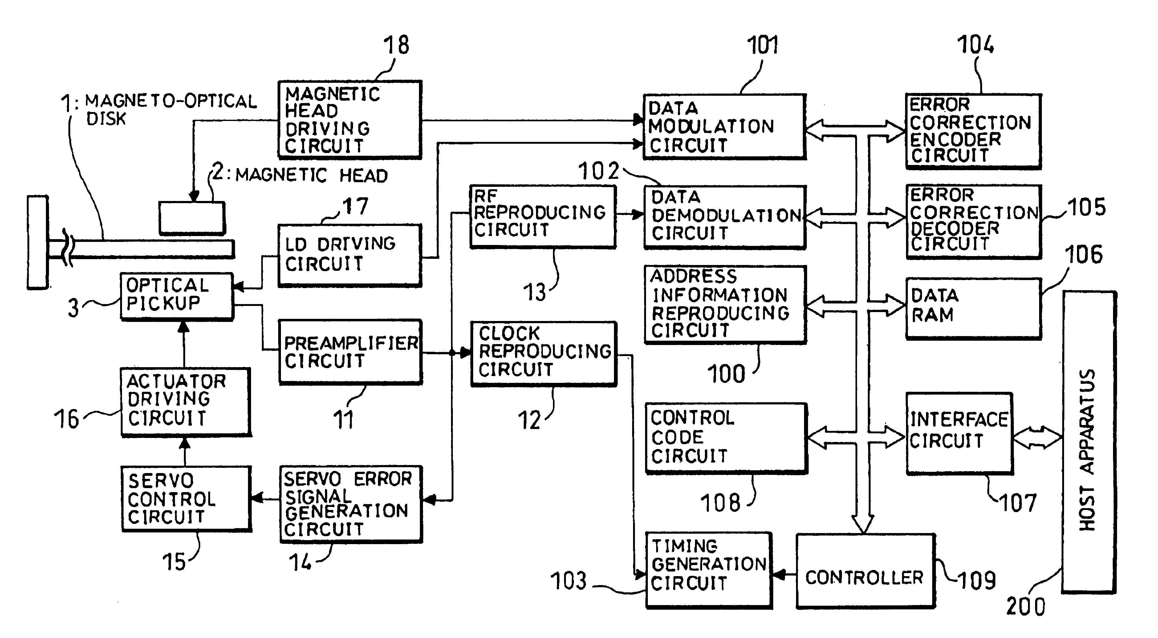
[0043]Referring to FIGS. 1 through 5, the following description will discuss an optical disk recording method and an optical disk recording and reproducing apparatus in accordance with Embodiment 1.

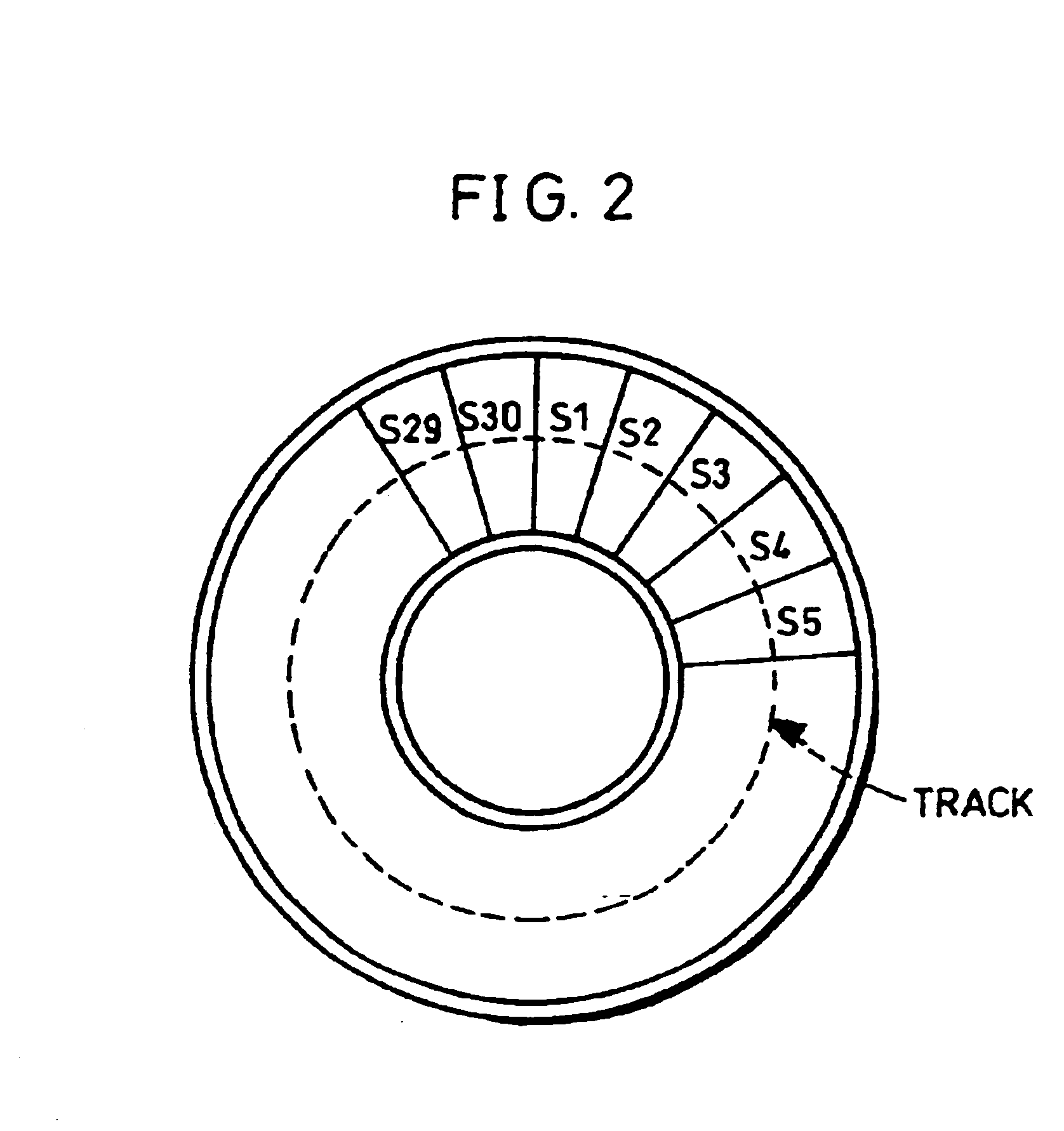
[0044]FIG. 2 is an explanatory drawing of an optical disk to which the recording method of the present Embodiment is applied. The optical disk shown in FIG. 2 is a magneto-optical disk having a track format of a sample servo system. One circuit of the spiral track of this magneto-optical disk is divided into 30 physical sectors (frames).

[0045]FIG. 3(a) is an explanatory drawing that shows the layout of segments on the track of the optical disk. Each segment consists of a data field DF on which a servo field SF having a length corresponding to 2 bytes and data of 50 bytes are recorded. Therefore, in FIG. 3(a), data of 50 bytes are recorded between areas (servo fields SF) formed as concave and convex sections on the substrate. Here, each frame consists of 48 data segments on w...

embodiment 2

[Embodiment 2]

[0101]Referring to FIGS. 6(a) and 6(b), the following description will discuss Embodiment 2 of the present invention. Here, in the same manner as Embodiment 1, an explanation will be given of a case in which the present invention is applied to a magneto-optical disk shown in FIG. 2 and FIGS. 3(a) and 3(b). Those members that have the same functions and that are described in Embodiment 1 are indicated by the same reference numerals; and the description thereof is omitted.

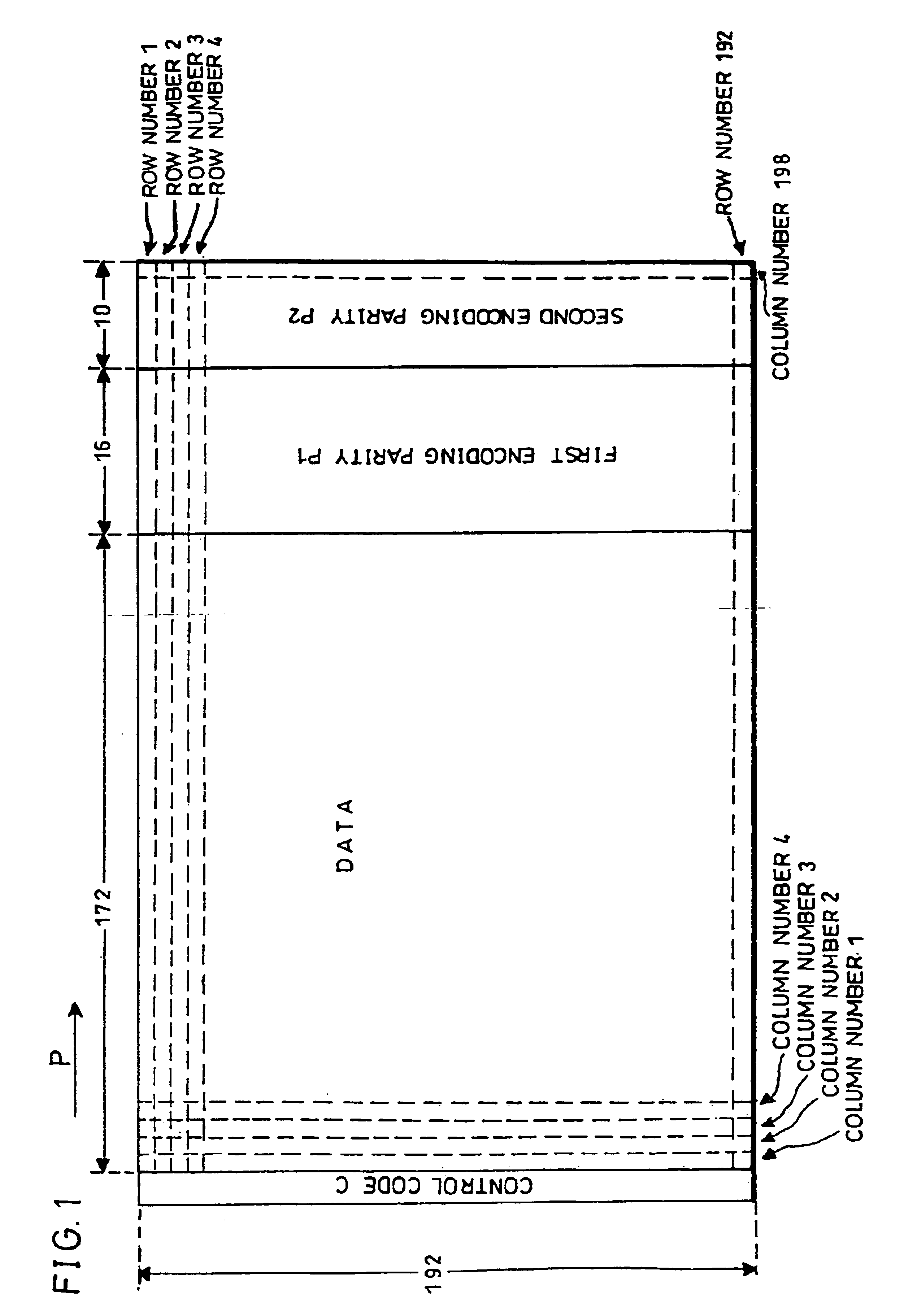
[0102]FIGS. 6(a) and 6(b) are explanatory drawings which relates to an error correction sequence of a recording format in the above-mentioned magneto-optical disk, and which shows an arrangement of a data block that constitutes a unit for an error-encoding process. Here, the size of the data block, the size of the logical sector and the first and second encoding processes are the same as those of Embodiment 1. Moreover, the arrangement in which the control code indicating the row number, etc. in the two...


PUM

PropertyMeasurementUnit
thicknessaaaaaaaaaa
lengthaaaaaaaaaa
areaaaaaaaaaaa

Abstract

In a recording method for an optical disk, an optical disk is used, in which concave and convex areas formed as concave and convex sections on the disk substrate are arranged along a track with constant intervals and a recording area for recording data of a predetermined number of units is placed between the concave and convex areas arranged with constant intervals. Upon recording information on this optical disk, a two-dimensional array is formed by adding addition data to input data, a first encoding parity is added to the two dimensional array by carrying out a first encoding process that forms a code sequence by using a data alignment in a diagonal direction, and a second encoding parity is added to the resulting two dimensional array by carrying out a second encoding process that forms a code sequence by using a data alignment in a row direction so that a second two dimensional array is formed. Then, data is successively recorded in the row direction. With this arrangement, it is possible to reduce the occurrence of an incorrectable error in the optical disk in which the recording areas are placed along the track with constant intervals.

Description

FIELD OF THE INVENTION[0001]The present invention relates to an optical disk recording method by which data is subjected to an error-correction encoding process, and recorded, an optical disk recording apparatus, an optical disk reproducing apparatus and an optical disk.BACKGROUND OF THE INVENTION[0002]In an optical disk, an error tends to occur in reproduced data due to a defect in a disk substrate or recording layer and dust and scratches on the surface of a disk substrate. In particular, in recent years, since the recording density has become higher and since the thickness of the disk substrate has become as thin as 0.6 mm, the above-mentioned defect, dust, scratches, etc. are more likely to cause an error.[0003]For this reason, in the optical disk recording and reproducing apparatus, there have been high demands for those apparatuses which have a superior correcting capability in the error-correction encoding process in which an error in data reproduced at the time of disk playb...

Claims


Application Information

Patent Timeline
Patent Type & Authority Patents(United States)
IPC IPC(8): G11B27/30G11B5/76G11B7/007G11B20/12G11B20/18H03M13/11H03M13/15H03M13/29
CPCG11B20/1217H03M13/2921G11B20/1833H03M13/15G11B20/12
Inventor YAMAGUCHI, TAKESHIMAEDA, SHIGEMI
Owner SHARP KK
Why Eureka
Try Eureka