
Multi-pulse HVDC system using auxiliary circuit

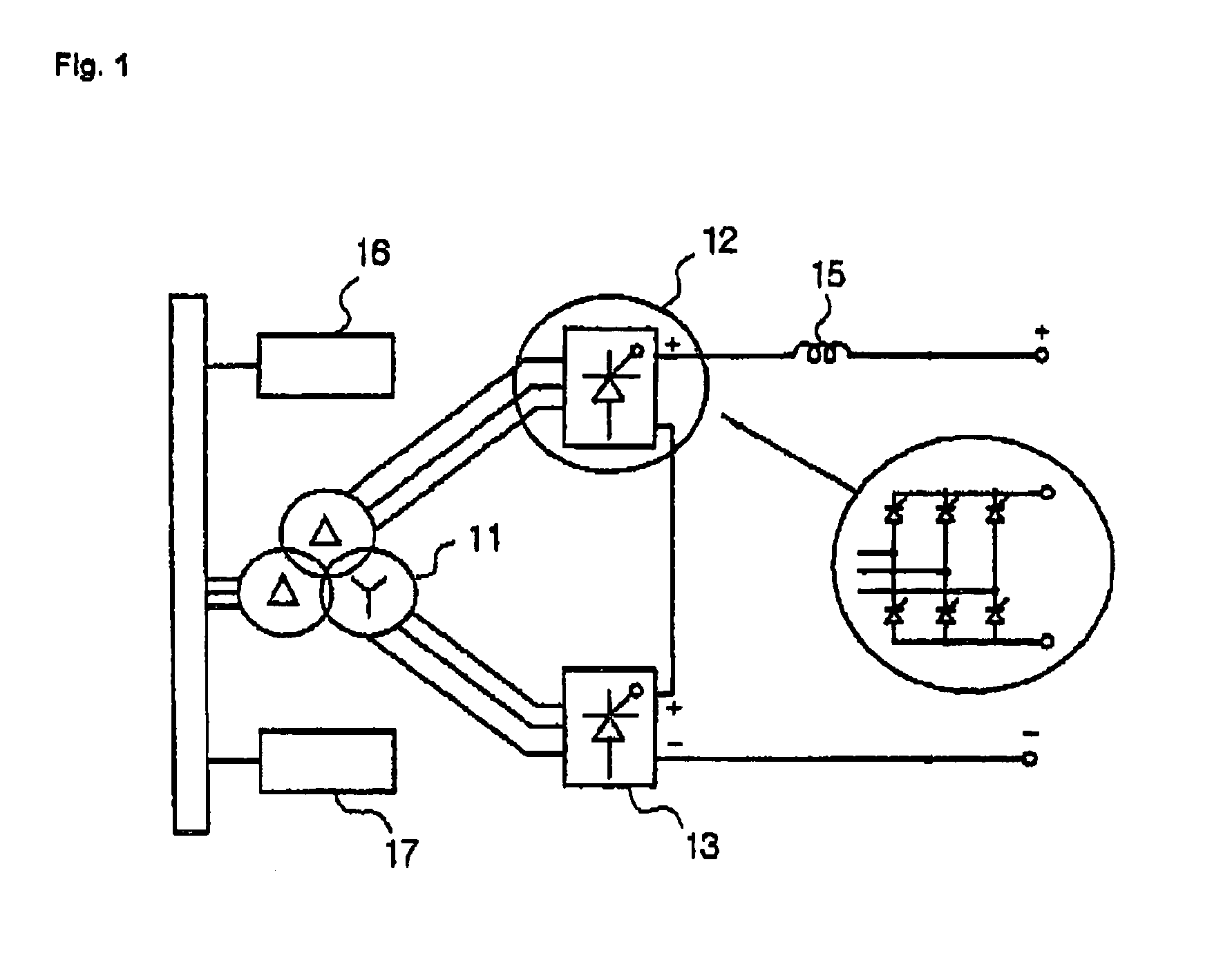
a hvdc system and auxiliary circuit technology, applied in the field of multipulse hvdc systems, can solve the problems of harmonic problems, affecting the use of end gto, and affecting the effect of gto use,

Inactive Publication Date: 2006-06-13
KOREA ELECTRIC POWER CORP
View PDF6 Cites 4 Cited by
  • Summary
  • Abstract
  • Description
  • Claims
  • Application Information

AI Technical Summary

Benefits of technology

[0018]Accordingly, it is an object of the present invention to provide a multi-pulse HVDC system u

Problems solved by technology

However, in the above AC power transmission, there is a certain limit in a long distance transmission due to a capacitive load between a transmission cable and ground and an inductance existing in a transmission cable.
Since the direct current transmission method is implemented based on a thyristor which is capable of performing a phase control, a harmonic problem occurs.
Among the above methods, the self-arc extinguishing HVDC system implemented using IGBT end GTO has many problems for actually using the same since a technical review is not ended.
If the number of pulses of a thyristor exceeds 12 pulses, since the harmonic is decreased, the capacity of the harmonic filter is advantageously decreased, but an economical burden problem occurs because a thyristor stack must be additionally provided.
The above method has disadvantages in an economical basis as the number of the thyristors is increased.
Therefore, since the current reverse flow auxiliary circuit is additionally connected to the conventional 12-pulse thyristor HVDC system for thereby performing the operation based on the 24-pulse thyristor HVDC system, it is not economical.

Method used


Image

  • Multi-pulse HVDC system using auxiliary circuit
  • Multi-pulse HVDC system using auxiliary circuit
  • Multi-pulse HVDC system using auxiliary circuit

Examples


Embodiment Construction

[0032]The constructions and operations of the present invention will be explained with reference to the accompanying drawings.

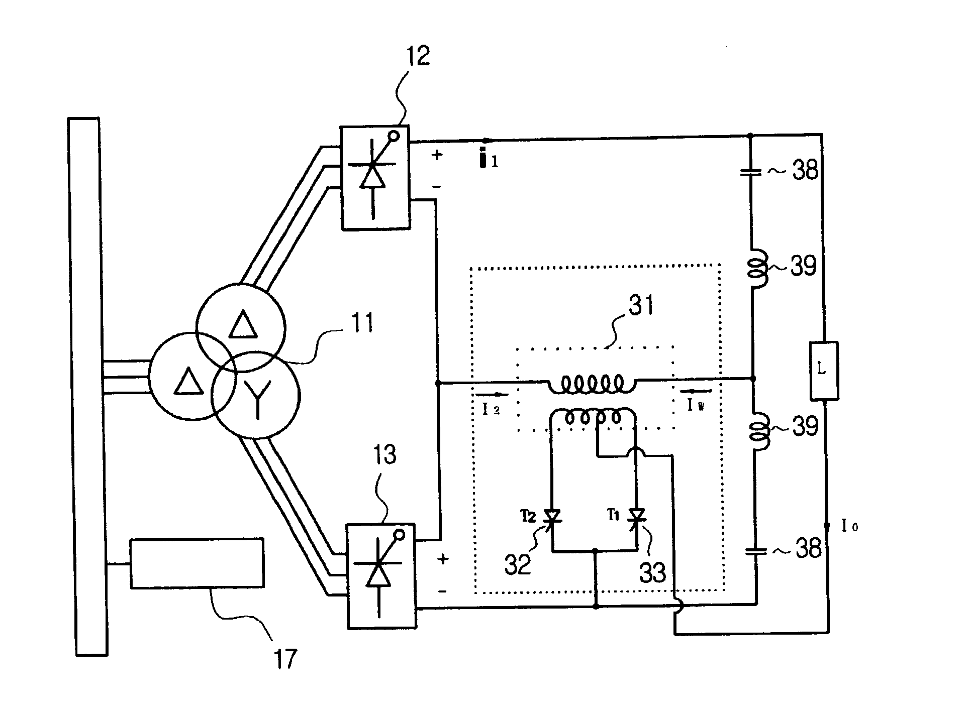
[0033]FIG. 5 is a circuit diagram illustrating a 24-pulse HVDC system using an auxiliary circuit according to the present invention. The above construction is implemented in such a manner that the number of two double-winding transformers is decreased to one in the auxiliary circuit of FIG. 4 for thereby implementing the same operation as a 24-pulse thyristor HVDC system.

[0034]An upper side thyristor converter 12 and a lower side thyristor converter 13 are installed in the Δ-Δ-Y transformer 11. Two current smoothing reactors 39 and a direct current voltage dividing condenser 38 are installed between the upper side thyristor converter 12 and the lower side thyristor converter 13. In addition, there is provided two thyristors(T2, T1) 32, 33 each connected to one double-winding transformer 31.

[0035]The auxiliary circuit includes two current smoothing reactors 39...


PUM


Abstract

The present invention relates to a multi-pulse HVDC system which is capable of minimizing the number of thyristors by providing a thyristor auxiliary circuit in a conventional 12-pulse thyristor HVDC(High Voltage Direct Current), not using an additional stack of a thyristor and which is implemented based on an auxiliary circuit having a multi-pulse thyristor HVDC system like 24-pulse / 36-pulse / 48-pulse converters. The multi-pulse HVDC system is characterized in that an upper side thyristor converter 12 and a lower side thyristor converter 13 are installed in a Δ-Δ-Y transformer 11, and two current smoothing reactor 39 and a direct voltage dividing condenser 38 are installed between the upper side thyristor converter 12 and the lower side thyristor converter 13, and two thyristors 32, 33: T2 and T1 are connected to one double winding transformer 31.

Description

BACKGROUND OF THE INVENTION[0001]1. Field of the Invention[0002]The present invention relates to a multi-pulse HVDC system which is capable of minimizing the number of thyristors by providing a thyristor auxiliary circuit in a conventional 12-pulse thyristor HVDC(High Voltage Direct Current), not using an additional stack of a thyristor and which is implemented based on an auxiliary circuit having a multi-pulse thyristor HVDC system like 24-pulse / 36-pulse / 48-pulse converters.[0003]2. Description of the Background Art[0004]An AC voltage and current outputted from a generator is a low current-large current. When transmitting power, the voltage and current are transmitted in a long distance in a low current type, maintaining a high voltage using a high voltage or ultra-high voltage transformer due to a loss in a conductor by a large current. However, in the above AC power transmission, there is a certain limit in a long distance transmission due to a capacitive load between a transmiss...

Claims


Application Information

Patent Timeline
IPC IPC(8): H01H47/18H02J1/00H02J3/26H02J3/36H02M1/12H02M1/14H02M7/155H02M7/19
CPCH02J3/36H02M7/19Y02E60/60H02J3/26
Inventor KIM, CHAN KIJUNG, GIL JOKHO, BONG EONAN, YONG HOCHOI, SE HWANCHOI, JONG KIYANG, BYEONG MO
Owner KOREA ELECTRIC POWER CORP
Learn More