
High current inductive coupler and current transformer for power lines

a technology of inductive coupler and current transformer, which is applied in the direction of electrical controller, coupling device connection, instruments, etc., can solve the problem of limiting the maximum power frequency current, and achieve the effect of preventing overheating and high magnetic permeability

Active Publication Date: 2006-06-13
ERICSSON INC
View PDF13 Cites 232 Cited by
  • Summary
  • Abstract
  • Description
  • Claims
  • Application Information

AI Technical Summary

Benefits of technology

"The present invention is related to a device that couples high-frequency data signals between a power distribution system and a modem device. The device includes a power line data coupler that uses a high-frequency magnetic core with high magnetic permeability at data communication frequencies. The coupler has a secondary winding that is connected to the power line primary winding and a choke coil or gas tube surge arrestor to cancel out secondary current. The coupler is designed to have a low impedance at power frequencies to minimize the impact of the secondary current on the power line current. The device also includes a system for sensing current on the power distribution system power line using a current transformer and a signal acquisition device. The invention provides a solution for safely and efficiently coupling high-frequency data signals between a power distribution system and a modem device."

Problems solved by technology

Such saturation may limit the maximum power frequency current that may be induced in the secondary winding, and prevent its overheating.

Method used


Image

  • High current inductive coupler and current transformer for power lines
  • High current inductive coupler and current transformer for power lines
  • High current inductive coupler and current transformer for power lines

Examples


Embodiment Construction

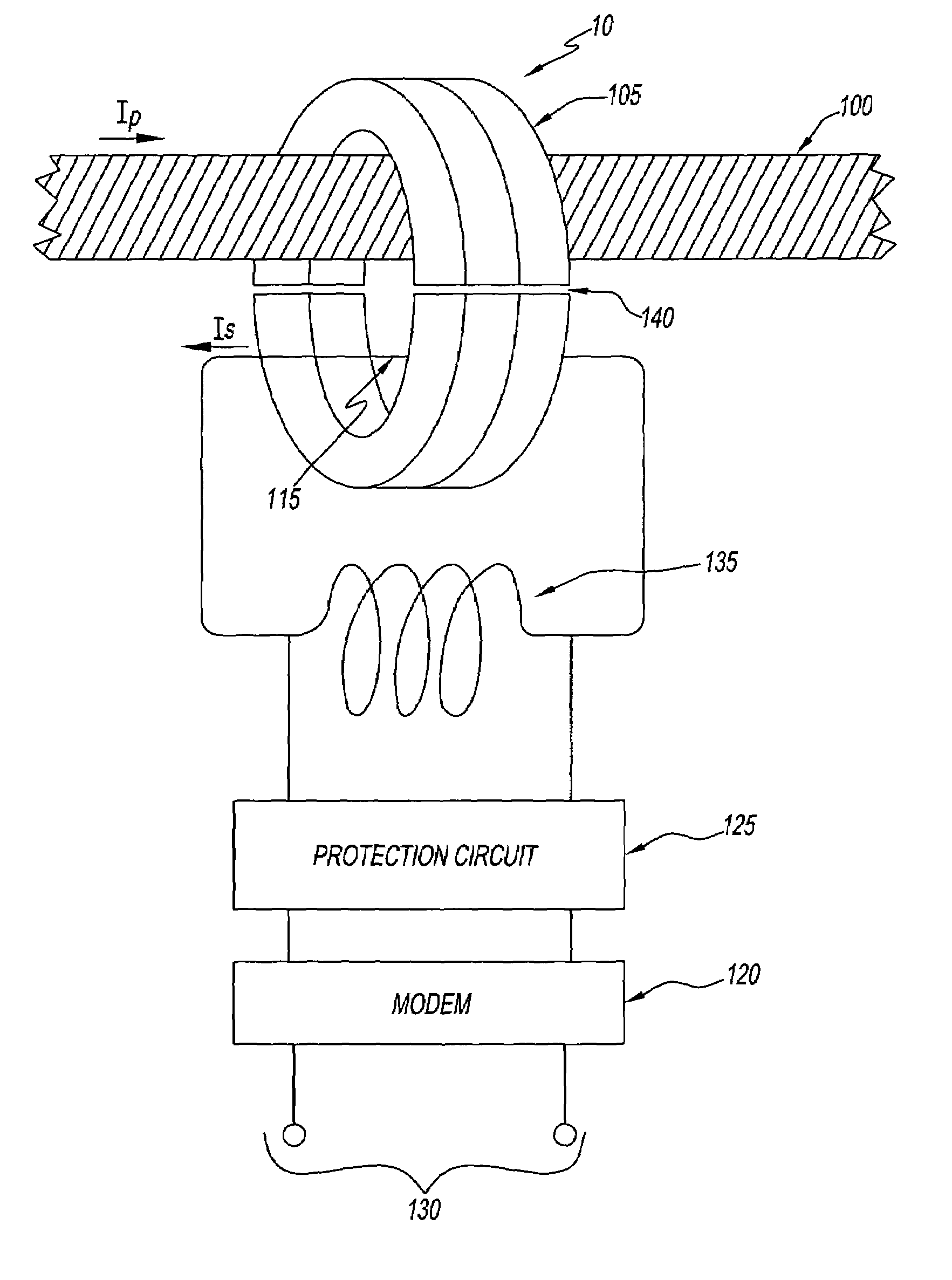
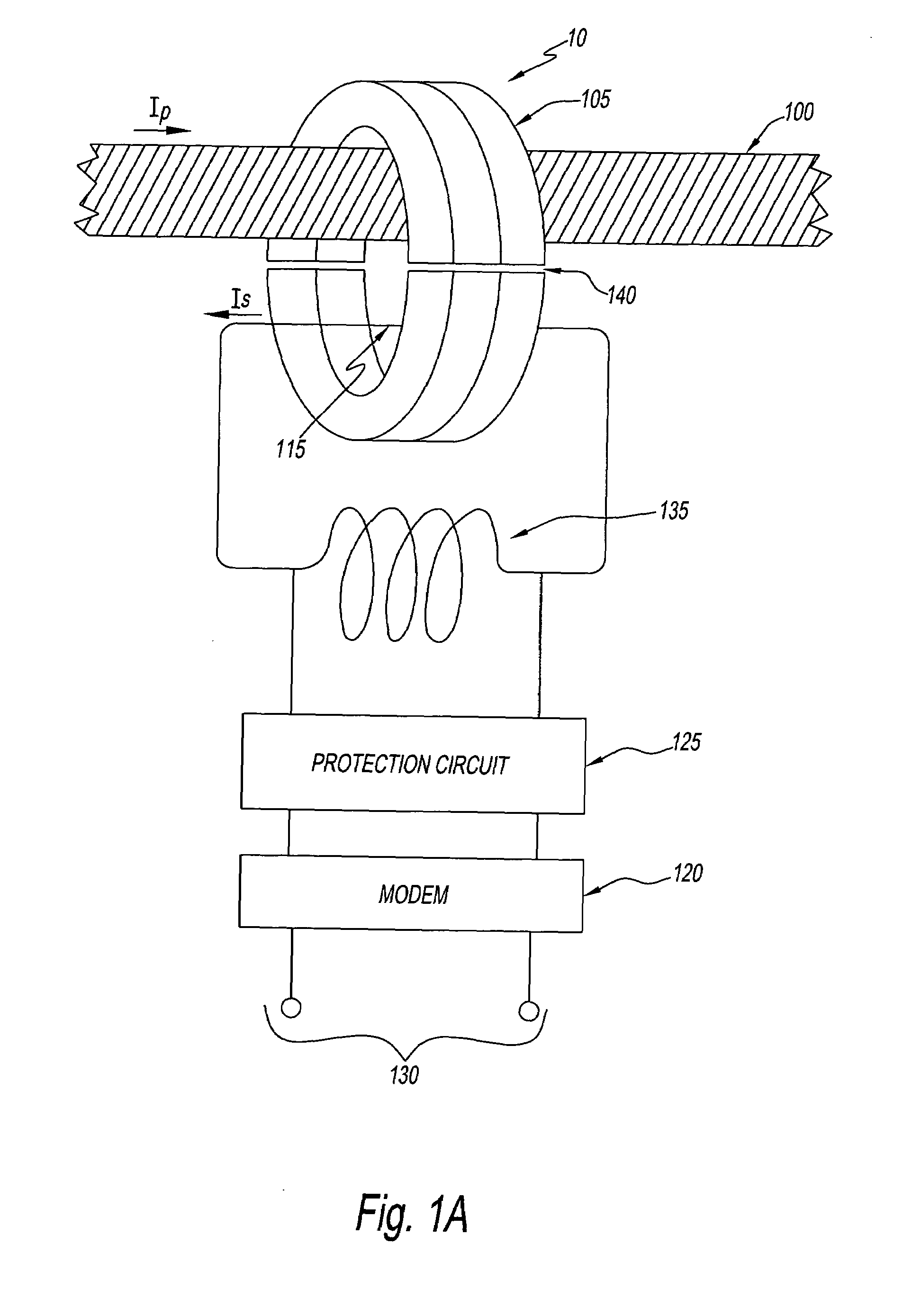
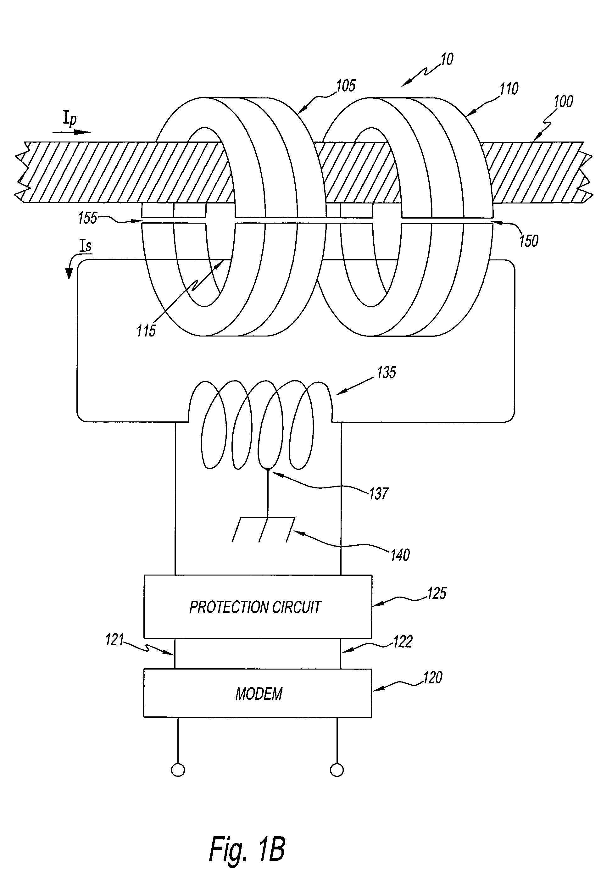
[0023]The magnitude of primary power line current that can be accommodated before an onset of significant core saturation can be greatly increased by providing a secondary winding in which flows power frequency current in a direction opposite to the primary power line current. In a secondary winding whose terminals are connected to each other via a short circuit or very low impedance, a current is induced, of magnitude nearly equal to that of the primary current. Under these conditions, a magnetomotive force driving a core, through which the primary and secondary windings are routed, will be reduced to an algebraic sum of respective current-times-number-of-turns in the primary and secondary windings, and be much lower than the primary current alone. This permits an increase of allowable primary current, before saturation begins.

[0024]The conditions needed to induce substantial current in the secondary winding include limiting impedance in the shorted winding circuit to be much less ...


PUM

PropertyMeasurementUnit
frequencyaaaaaaaaaa
frequencyaaaaaaaaaa
magnetic permeabilityaaaaaaaaaa

Abstract

There is provided an inductive power line data coupler. The coupler includes (a) a magnetic core having a high magnetic permeability at a data communication frequency and being configured to allow a power line of a power distribution system to be routed through the magnetic core to serve as a primary winding, (b) a data signaling circuit that provides a secondary winding through the magnetic core for coupling a data signal between the power line and a communication device, and (c) a choke coil coupled to the data signaling circuit for creating a flux-canceling power frequency current opposite in direction and comparable in magnitude to a power frequency current. The coupler may also include a circuit for sensing a level of current in the power line.

Description

CROSS REFERENCE TO RELATED APPLICATIONS[0001]The present application is claiming priority of (a) U.S. Provisional Patent Application Ser. No. 60 / 376,377, filed on Apr. 29, 2002, and (b) U.S. Provisional Patent Application Ser. No. 60 / 416,603, filed on Oct. 7, 2002.BACKGROUND OF THE INVENTION[0002]1. Field of the Invention[0003]The invention generally relates to power line communications, and more particularly, to avoiding magnetic saturation in a power line inductive coupler.[0004]2. Description of the Related Art[0005]In a power line communication system, power frequency is typically in a range of 50–60 Hertz and a data communication signal frequency is typically in a range of 1–50 MHz. An inductive coupler for coupling modulated data onto and off of power lines includes a magnetic core through which pass the power line and a secondary winding. This is described, for example, in patent application Ser. No. 09 / 752,705, filed Dec. 28, 2000, patent application Ser. No. 10 / 082,063, fil...

Claims


Application Information

Patent Timeline
Patent Type & Authority Patents(United States)
IPC IPC(8): G05B11/01H01R13/66H01F38/14H01R13/68H04B3/56
CPCH01R13/66H01R13/6666H04B3/56H01R13/68H04B2203/5487H04B3/54H04M11/04
Inventor CERN, YEHUDA
Owner ERICSSON INC
Learn More