
Methods and apparatus for measuring wind turbine blade deflection

a technology of wind turbine blades and measuring methods, which is applied in the field of wind turbine blade deflection measurement methods and apparatuses, can solve the problems of rotor blade deflection that produces fatigue in the rotor blades and other wind turbine components, and increases the risk of one of the rotor blades striking the wind turbine tower

Active Publication Date: 2006-06-13
GENERAL ELECTRIC CO
View PDF5 Cites 64 Cited by
  • Summary
  • Abstract
  • Description
  • Claims
  • Application Information

AI Technical Summary

Problems solved by technology

Due to this increase in size and decrease in weight, the rotor blades are subject to greater deflection forces.
However, due to the greater deflection forces, the risk of one of the rotor blades striking the wind turbine tower is increased.
In addition, rotor blade deflection produces fatigue in the rotor blades and other wind turbine components.
However, these techniques increase assembly and maintenance time, and increase the complexity of obtaining data relating to the rotor blade deflection.
Accordingly, measurement techniques of the kind presently in use have not previously provided blade deflection measurements in a cost effective and reliable manner.

Method used


Image

  • Methods and apparatus for measuring wind turbine blade deflection
  • Methods and apparatus for measuring wind turbine blade deflection
  • Methods and apparatus for measuring wind turbine blade deflection

Examples


Embodiment Construction

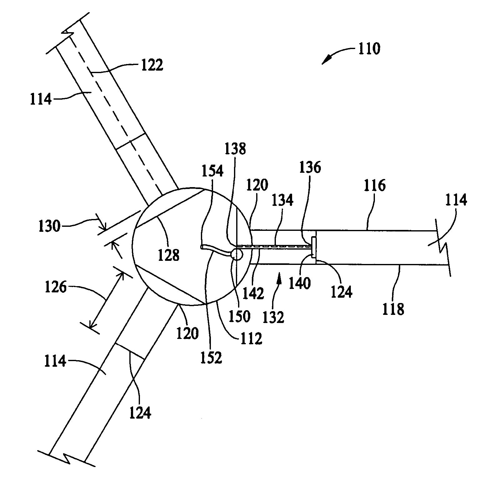
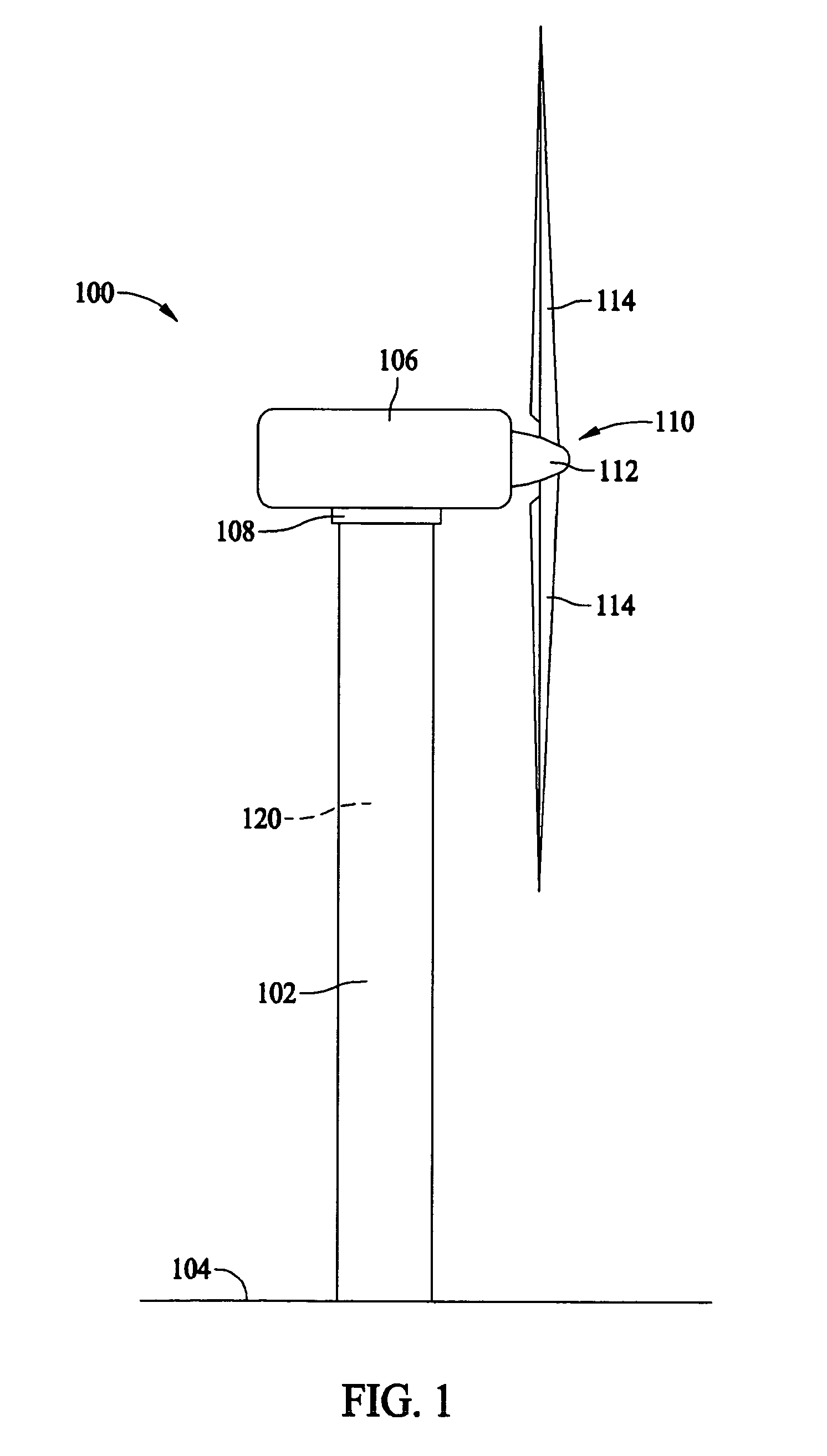
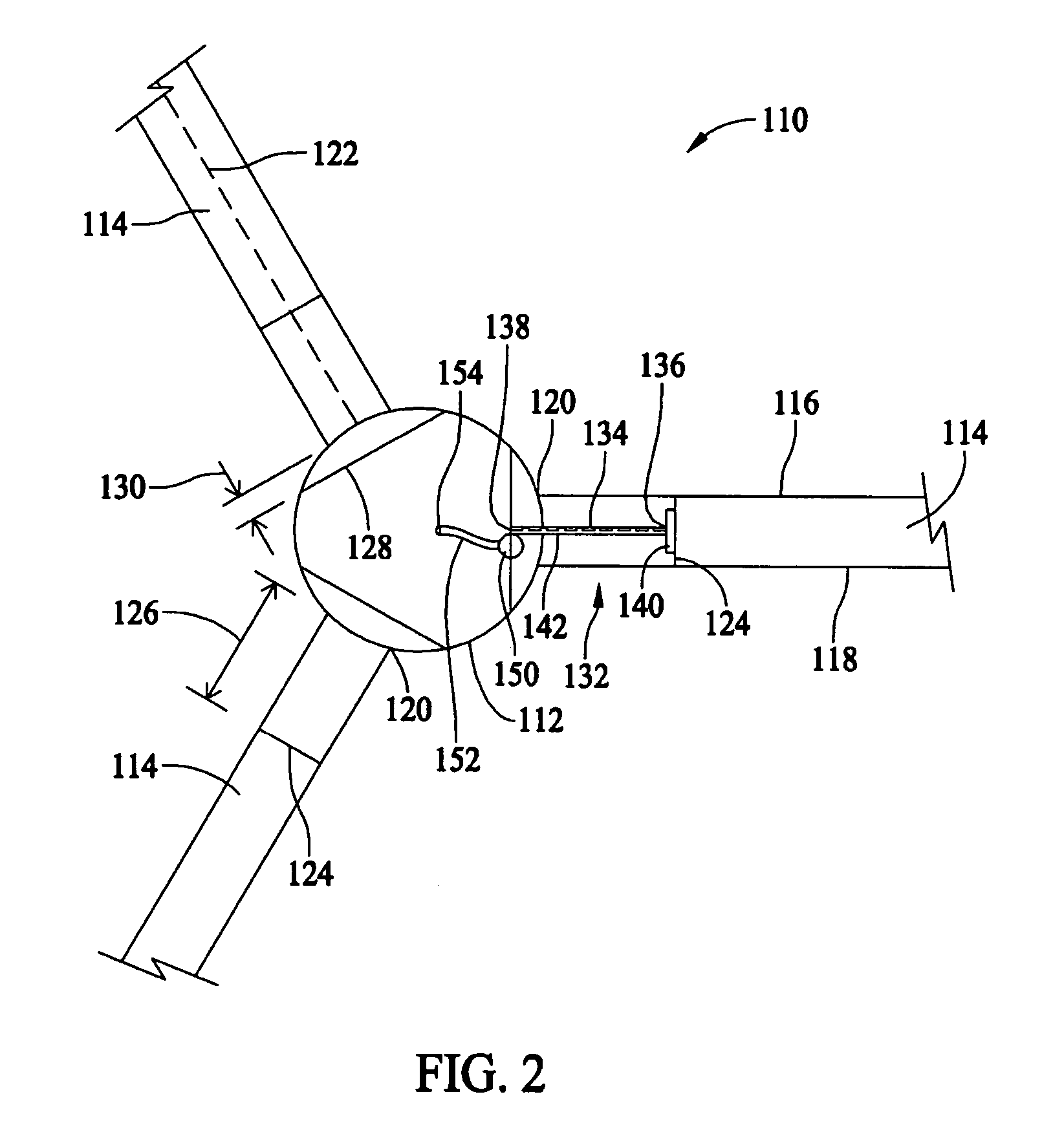
[0013]FIG. 1 is a side elevational view of a wind turbine 100, such as, for example, a horizontal axis wind turbine. Wind turbine 100 includes a tower 102 extending from a supporting surface 104, a nacelle 106 mounted on a bedframe 108 of tower 102, and a rotor 110 coupled to nacelle 106. Rotor 110 includes a hub 112 and a plurality of rotor blades 114 coupled to hub 112. In the exemplary embodiment, rotor 110 includes three rotor blades 114. In an alternative embodiment, rotor 110 includes more or less than three rotor blades 114. In the exemplary embodiment, tower 102 is fabricated from tubular steel and includes a cavity 120 extending between supporting surface 104 and nacelle 106. Alternatively, tower 102 may be, for example, a lattice tower. It is appreciated, however, that the benefits and advantages of the invention may occur in a variety of structures, such as wind turbine 100, that have a rotor, such as rotor 110, and rotor blades, such as rotor blades 114. As such, while t...


PUM


Abstract

A method for determining rotor blade deflection, wherein a rotor blade is coupled to a hub, includes coupling a first end of a beam to the rotor blade, positioning a second end of the beam adjacent the hub, measuring the deflection of the beam using at least one sensor, and determining the deflection of the blade based on the deflection of the beam.

Description

BACKGROUND OF THE INVENTION[0001]This invention relates generally to wind turbines, and more particularly to methods and apparatus for measuring wind turbine blade deflection.[0002]Wind power is quickly becoming a growing energy source around the world. As such, wind turbines are increasing in size and capacity. Specifically, to increase energy output, rotor blade length is increased while rotor blade weight is decreased. Due to this increase in size and decrease in weight, the rotor blades are subject to greater deflection forces. However, due to the greater deflection forces, the risk of one of the rotor blades striking the wind turbine tower is increased. In addition, rotor blade deflection produces fatigue in the rotor blades and other wind turbine components. To minimize fatigue, many modern wind turbines use rotor blade pitch control strategies that require measuring the deflection of one or more rotor blades.[0003]Known wind turbines include sensors for detecting rotor blade ...

Claims


Application Information

Patent Timeline
Patent Type & Authority Patents(United States)
IPC IPC(8): F03B15/06
CPCF03D11/0091Y02E10/722F05B2270/8041F05B2270/33F03D17/00
Inventor LEMIEUX, DAVID LAWRENCEAVAGLIANO, AARON JOHNSMOLENSKI, JOSEPH LUCIANDEMUTH, RUSSELL STEPHEN
Owner GENERAL ELECTRIC CO
Learn More