
Automatic drilling system

a drilling system and automatic technology, applied in the direction of drilling pipes, rotary drilling, borehole/well accessories, etc., can solve the problems of high cost and time consumption of drilling wells, and high cost and time associated with well construction

Active Publication Date: 2006-06-13
NOBLE DRILLING SERVICES LLC
View PDF30 Cites 83 Cited by
  • Summary
  • Abstract
  • Description
  • Claims
  • Application Information

AI Technical Summary

Benefits of technology

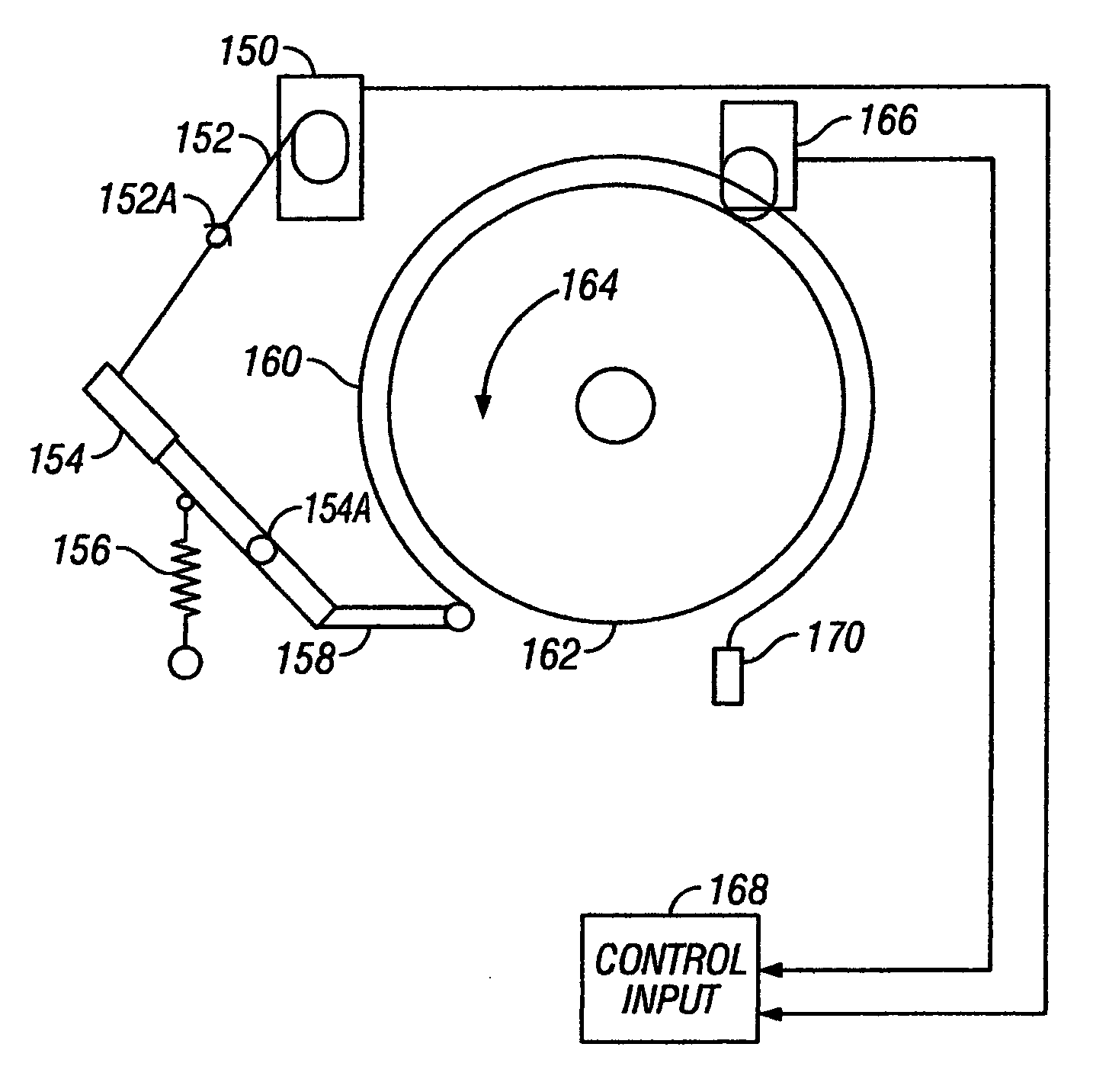
[0016]One aspect of the invention is an automatic drilling system which includes an electric servo motor operatively coupled to a winch brake control, a servo controller operatively coupled to the servo motor, and a drum position encoder rotationally coupled to a winch drum. The controller is adapted to operate the servo motor in response to measurements of position made by the encoder so that a selected rate of rotation of the drum is maintained.

Problems solved by technology

Drilling boreholes in subsurface formations for oil and gas wells is very expensive and time consuming.
The cost associated with drilling a well is primarily time dependent.
However, cost and time associated with well construction can increase substantially if wellbore instability problems or obstacles are encountered during drilling.
Because of the complex nature of drilling, a weight on bit that is optimum for one set of conditions may not be optimum for another set of conditions.
One of the more difficult tasks performed by the driller is to maintain the WOB as nearly as possible at the most efficient value.
There are a number of electrical (eddy current) braking devices, hydraulic braking devices and electro-hydraulic devices well known in the art that perform braking control or its functional equivalent to control the rate of drum rotation (and consequent cable release) Manual control of WOB is difficult.
The foregoing devices and other electro-mechanical devices may be limited as to the particular drilling parameter that can be controlled, for example WOB, drilling fluid pressure and drum rotation speed.
Further, some of the foregoing devices may require extensive modifications to the drilling rig drawworks equipment to be installed.
Despite the apparent advantages, computer controlled drilling rig systems have not been widely used.
As described in the Brett et al. reference, hydraulic lift units, while effective, have been difficult to maintain and transport.
'530 patent cited above, while effective and adaptable to computer control, require expensive and extensive modification of the drawworks equipment.
Adapting computer control to conventional drawworks motion control devices has also been difficult.
A primary source of the difficulty is the fact that conventional drawworks friction brakes are band-type brakes.
This aspect of the typical band-type drawworks has made their response difficult to characterize.
As a result, it has been believed by those skilled in the art that computer control of conventional band-type brakes is impracticable.

Method used


Image

  • Automatic drilling system
  • Automatic drilling system
  • Automatic drilling system

Examples


Embodiment Construction

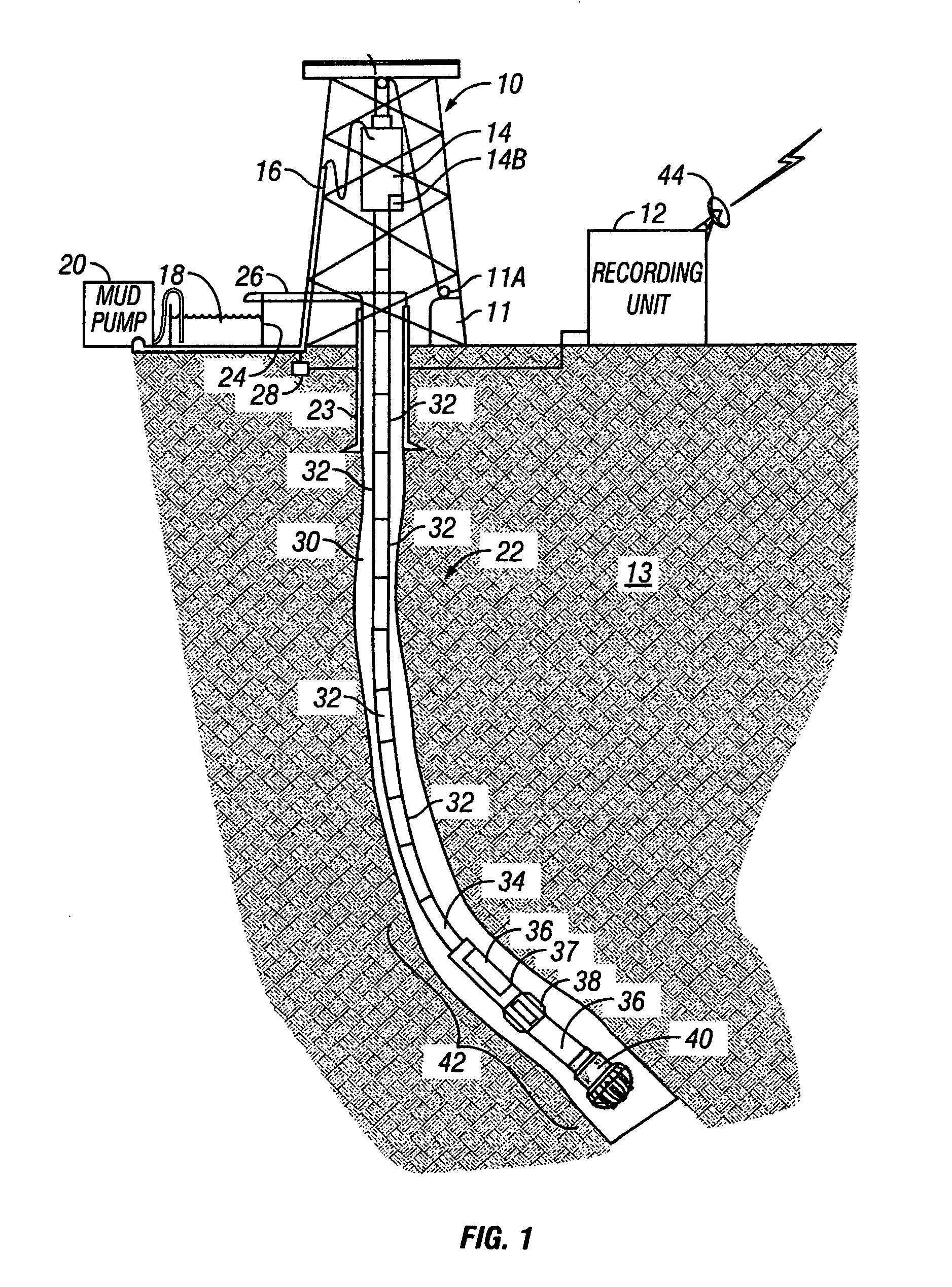
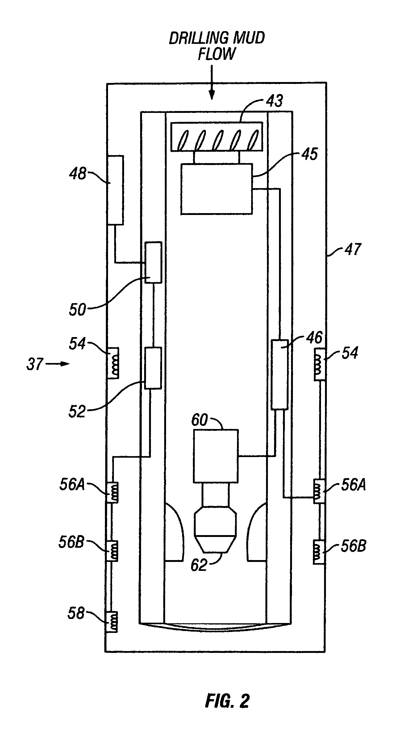
[0022]FIG. 1 shows a typical wellbore drilling system which may be used with various embodiments of the invention. A drilling rig 10 includes a drawworks 11 or similar lifting device known in the art to raise, suspend and lower a drill string. The drill string includes a number of threadedly coupled sections of drill pipe, shown generally at 32. A lowermost part of the drill string is known as a bottom hole assembly (BHA) 42, which includes, in the embodiment of FIG. 1, a drill bit 40 to cut through earth formations 13 below the earth's surface. The BHA 42 may include various devices such as heavy weight drill pipe 34, and drill collars 36. The BHA 42 may also include one or more stabilizers 38 that include blades thereon adapted to keep the BHA 42 roughly in the center of the wellbore 22 during drilling. In various embodiments of the invention, one or more of the drill collars 36 may include a measurement while drilling (MWD) sensor and telemetry unit (collectively “MWD system”), s...


PUM


Abstract

An automatic drilling system is disclosed which includes an electric servo motor operatively coupled to a winch brake control, a servo controller operatively coupled to the servo motor, and a drum position encoder rotationally coupled to a winch drum. The controller is adapted to operate the servo motor in response to measurements of position made by the encoder so that a selected rate of rotation of the drum is maintained.

Description

CROSS REFERENCE TO RELATED APPLICATION[0001]This application claims the benefit of U.S. Provisional Application No. 60 / 459,503, filed Apr. 1, 2003, and titled Automatic Drilling System.BACKGROUND OF INVENTION[0002]1. Field of the Invention[0003]The invention relates generally to drilling wellbores through subsurface earth formations. More particularly, the invention relates to a system for automatically controlling the rate of release of a drill string to maintain a selected control parameter during drilling.[0004]2. Background Art[0005]Drilling wellbores through the earth includes “rotary” drilling, in which a drilling rig or similar lifting device suspends a drill string which turns a drill bit located at the bottom end of the drill string. Equipment on the rig, such as a rotary table / kelly or a top drive turns the drill string. Some drill strings may include an hydraulically operated motor to rotate the bit in addition to or in substitution of rotating the drill string from the s...

Claims


Application Information

Patent Timeline
Patent Type & Authority Patents(United States)
IPC IPC(8): E21B3/06E21B44/00E21B19/08E21B44/02
CPCE21B44/02E21B19/08E21B19/084
Inventor POWER, DAVID J.GLASER, GERHARD P.
Owner NOBLE DRILLING SERVICES LLC
Learn More