
Configurable digital loudness compensation system and method

a digital loudness compensation and digital technology, applied in the field of digital circuits, can solve problems such as inapplicability, and achieve the effect of maximum listening pleasur

Inactive Publication Date: 2006-06-06
TEXAS INSTR INC
View PDF12 Cites 99 Cited by
  • Summary
  • Abstract
  • Description
  • Claims
  • Application Information

AI Technical Summary

Benefits of technology

[0005]Accordingly, there is a need for a loudness compensation system that offers flexibility and configurability in the shape of the loudness compensation curves and the mapping back to the recorded sound pressure level to achieve the maximum listening pleasure.
[0006]In accordance with the present invention, a flexible and configurable digital loudness compensation system and method are provided which eliminate or substantially reduce the disadvantages associated with prior loudness compensators.

Problems solved by technology

Although such understanding between recording and playback is desirable, it is not directly applicable because the sound pressure level of the music at the time of recording is typically not known.

Method used


Image

  • Configurable digital loudness compensation system and method
  • Configurable digital loudness compensation system and method
  • Configurable digital loudness compensation system and method

Examples


Embodiment Construction

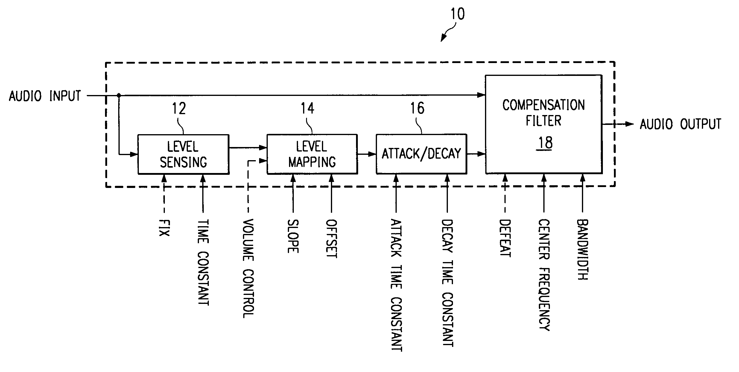
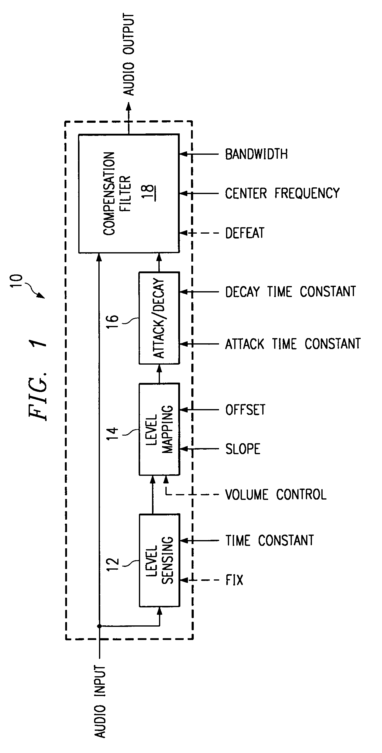
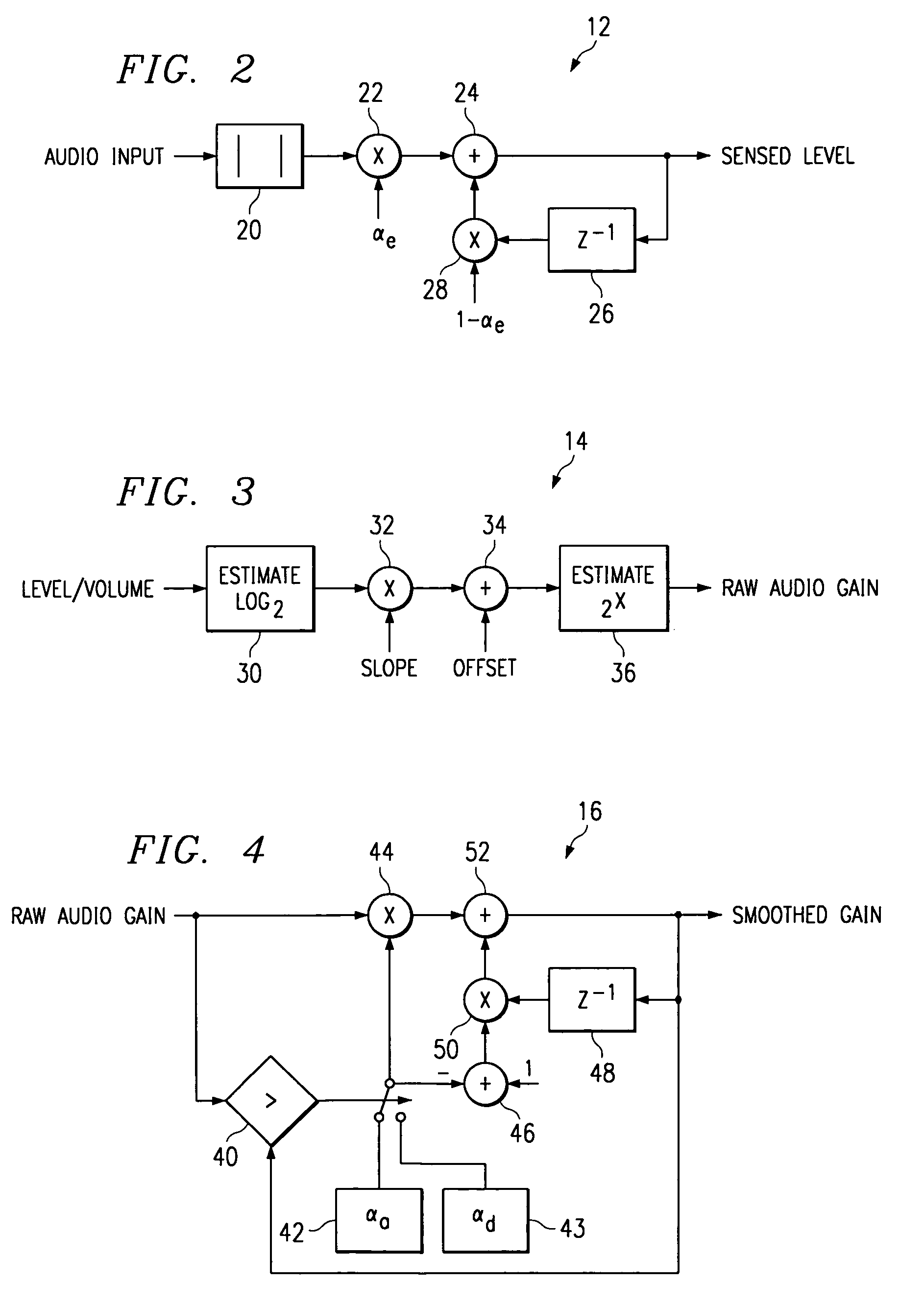
[0017]FIG. 1 is a simplified block diagram of an embodiment of a configurable digital loudness compensation system and method 10 constructed according to the teachings of the present invention. Only a single channel is shown for the sake of clarity. System and method 10 includes an automatic level sensing circuit subsystem or function 12, which receives the audio signal input and provides an estimate of the level of the signal over a predetermined period of time, indicated by the time constant input. Another input, fix, is a user-input which instructs level sensor 12 to maintain the gain of the loudness compensation at the current level. In this mode of operation, the offset input is a manual gain adjustment for loudness compensation and may be used to override the fix command.

[0018]The sensed level from level sensor 12 is provided to a level mapping circuit, subsystem, or function 14. Level mapper 14 applies a linear function, specified by a slope and an offset, to map the sensed l...


PUM


Abstract

An audio loudness compensation system includes a level sensor receiving an audio input signal and operable to estimate a level of the audio input signal over a first predetermined time period, and a level mapper receiving the estimated level and operable to map the estimated level to a raw audio gain in response to a slope setting and an offset setting. The system further includes an attack and decay filter receiving the raw audio gain and operable to smooth out increasing and decreasing changes in the raw audio gain in response to a second and, possibly a third predetermined time period, and a compensation filter receiving the smoothed raw audio gain and operable to modify the audio input signal in response to the smoothed raw audio gain, a center frequency setting and a bandwidth setting, and generate a loudness compensated audio output signal.

Description

RELATED PATENT APPLICATION[0001]This patent application is related to U.S. non-provisional Ser. No. 09 / 407,552, entitled Digital Audio Dynamic Range Compressor And Method, filed on Sep. 27, 1999; U.S. non-provisional Ser. No. 09 / 408,095, entitled Digital Tone Control with Linear Step Coefficients, filed on Sep. 27, 1999; U.S. non-provisional Ser. No. 09 / 401,422, entitled Digital Graphic Equalizer Control System and Method, filed on Sep. 22, 1999; and U.S. non-provisional Ser. No. 09 / 192,981, titled Digital Signal Processing Circuits, Systems, and methods Implementing Approximations for Logarithm and Inverse Logarithm, filed on Nov. 16, 1998, all of which are incorporated herein by reference.TECHNICAL FIELD OF THE INVENTION[0002]This invention is related in general to the field of digital circuits. More particularly, the invention is related to a configurable digital loudness compensation system and method.BACKGROUND OF THE INVENTION[0003]It has been long understood that the human ea...

Claims


Application Information

Patent Timeline
IPC IPC(8): H03G3/00H03G5/00
CPCH03G5/18
Inventor ALLRED, RUSTIN W.
Owner TEXAS INSTR INC
Learn More