
Shower head structure

a shower head and structure technology, applied in dental surgery, lighting and heating apparatus, combustion types, etc., can solve the problems of uncompetitive market and limited practical use of conventional showerheads, and achieve the effect of improving use, efficient boosting interest and function, and being more competitive on the mark

Inactive Publication Date: 2006-06-06
CHUNG CHENG FAUCET
View PDF4 Cites 104 Cited by
  • Summary
  • Abstract
  • Description
  • Claims
  • Application Information

AI Technical Summary

Benefits of technology

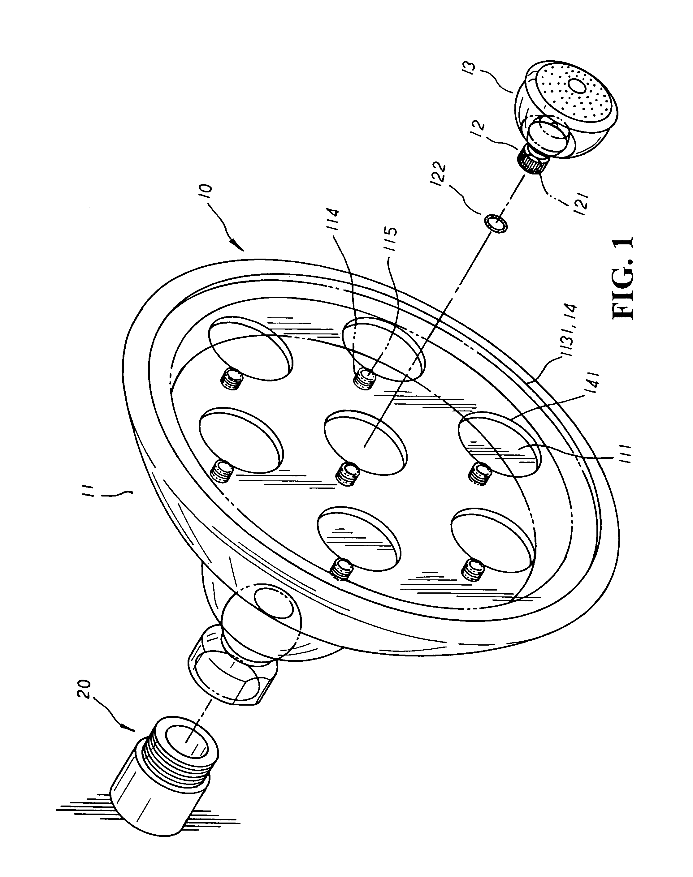
[0003]It is, therefore, the primary purpose of the present invention to provide a shower head structure, including a showerhead made up of a main body adjustably mounted to a water outlet coupling tube and rotated in any angles wherein the main body has a limiting separation board properly preset at one side thereof to divide a water-collecting space and a concaved space at both sides thereby, and a plurality of tubular water guiding conduits protruding at preset positions of the limiting separation board thereon to be securely registered with a plurality of universal connectors each having a water outlet spray head mounted thereto; therefore, the water outlet spray heads can be individually and freely adjusted in any angles, permitting the showerhead to deliver water from various angles simultaneously for showering purpose, efficiently boosting the interest and function of the present invention in practical use.

Problems solved by technology

As a result, the conventional showerhead is rather limited in practical use, which delivers water flow only in one spray pattern and from a certain fixed angle without the flexibility to verify the spray patterns or adjust the angles as desired.
Thus, the conventional showerhead is uncompetitive on the market.

Method used


Image

  • Shower head structure
  • Shower head structure
  • Shower head structure

Examples


Embodiment Construction

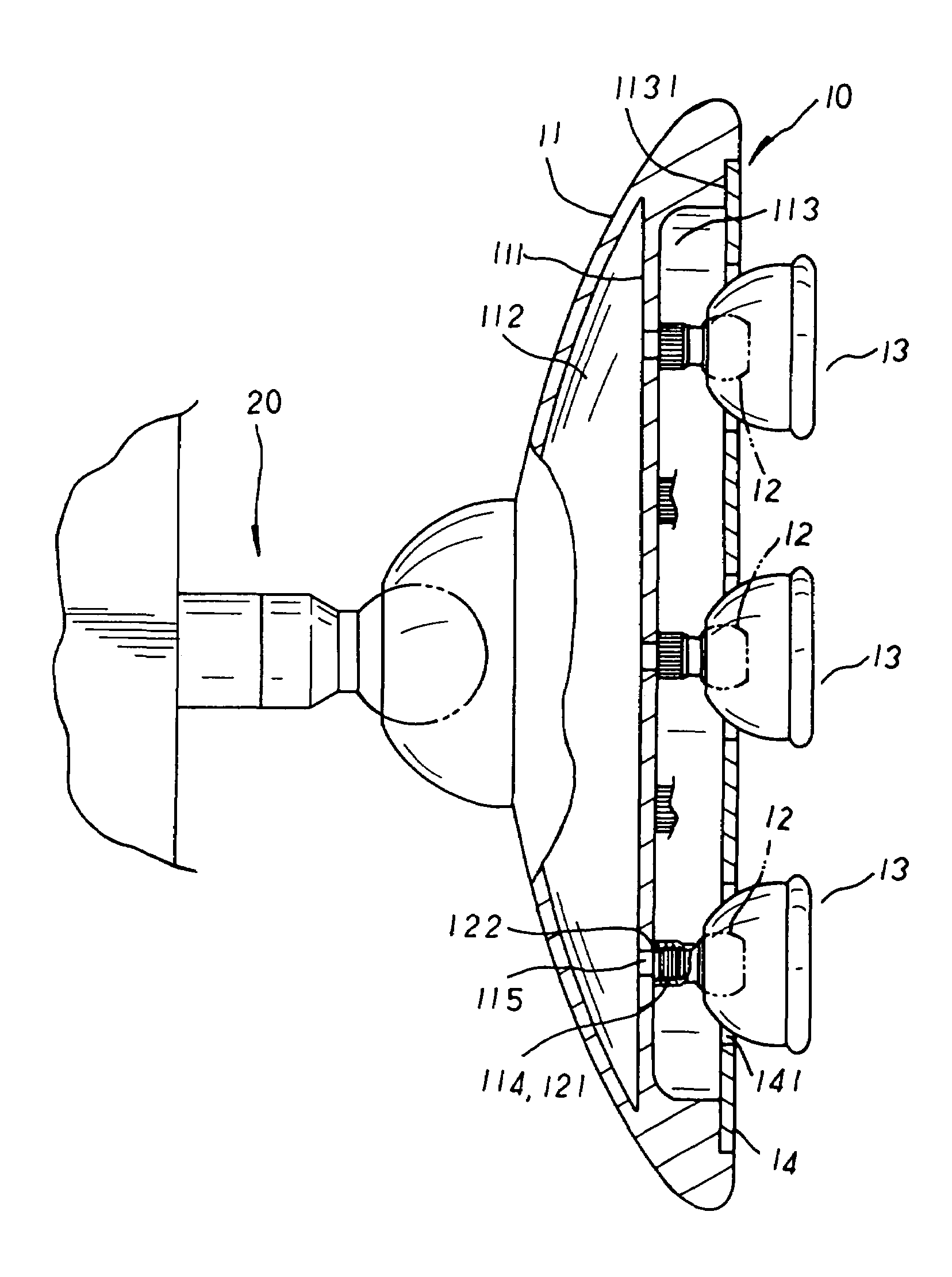
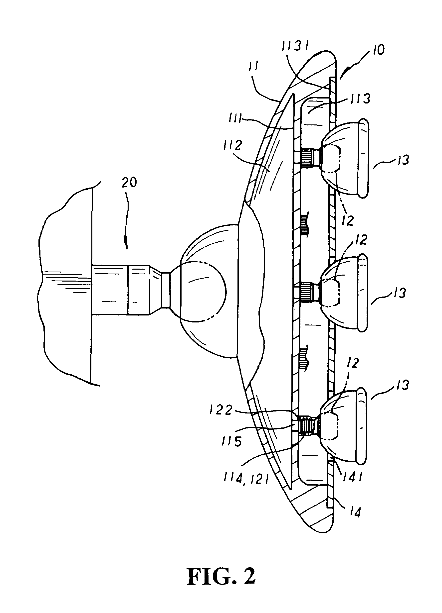
[0009]Please refer to FIGS. 1 to 2 inclusive. The present invention is related to a shower head structure, including a showerhead 10 made up of a main body 11 of a proper size that, adjustably mounted to a water outlet coupling tube 20, can be freely rotated in any angles. The main body 11 has a concaved groove disposed at one side thereof, and a limiting separation board 111 is properly preset at the concaved groove of the main body 11 therein to divide a water-collecting space 112 and a concaved space 113 at both sides thereby. A plurality of tubular water guiding conduits 115 each having external threads 114 disposed thereon are provided protruding at preset positions of the limiting separation board 111 thereon to communicate with both the water-collecting space 112 and the water outlet coupling tube 20 thereof, and a plurality of universal connectors 12 each having internal threads 121 disposed therein and a sealing ring 122 adapted thereto are securely registered with the exte...


PUM


Abstract

A shower head structure includes a showerhead made up of a main body adjustably mounted to a water outlet coupling tube and rotated in any angles wherein the main body has a limiting separation board properly preset at one side thereof to divide a water-collecting space and a concaved space at both sides thereby, and a plurality of tubular water guiding conduits protruding at preset positions of the limiting separation board thereon to communicate with both the water-collecting space and the water outlet coupling tube thereof. Each of the water guiding conduits is securely registered with a universal connector to which a water outlet spray head with various types of water outlet apertures such as net-like, tubular, or misty water outlet apertures disposed thereon is mounted thereby. Therefore, the water outlet spray heads can be individually and freely adjusted in any angles, permitting the showerhead to deliver water from various angles and in versatile patterns simultaneously for showering purpose, efficiently boosting the interest and function of the present invention in practical use.

Description

BACKGROUND OF THE INVENTION[0001]The present invention is related to a shower head structure, including a showerhead made up of a main body adjustably mounted to a water outlet coupling tube and rotated in any angles wherein the main body has a limiting separation board properly preset at one side thereof to divide a water-collecting space and a concaved space at both sides thereby, and a plurality of tubular water guiding conduits protruding at preset positions of the limiting separation board thereon to be securely registered with a plurality of universal connectors each having a water outlet spray head with various types of water outlet apertures disposed thereon mounted thereto. Therefore, the water outlet spray heads can be individually and freely adjusted in any angles, permitting the showerhead to deliver water from various angles and in versatile patterns simultaneously for showering purpose, efficiently boosting the interest and function of the present invention in practica...

Claims


Application Information

Patent Timeline
IPC IPC(8): B05B15/08A62C2/08A62C37/08B05B1/14E21F5/04B05B15/68
CPCB05B15/067B05B1/185B05B1/14B05B15/654
Inventor KO, SHI CHIA
Owner CHUNG CHENG FAUCET
Learn More