Method of calibrating a detector and calibration sphere for the same

a technology of calibration sphere and detector, which is applied in the field of method of calibrating a detector and a calibration object, can solve the problems of increasing the difficulty of automatic inspection of three-dimensional surfaces of golf balls and other round objects, and causing another image distortion, so as to achieve the effect of minimizing image distortion

Inactive Publication Date: 2006-06-06
ACUSHNET CO
View PDF19 Cites 7 Cited by
  • Summary
  • Abstract
  • Description
  • Claims
  • Application Information

AI Technical Summary

Benefits of technology

[0009]Hence, the present invention is directed to a method of calibrating a detector that minimizes image distortions.
[0016]The detector, which preferably includes a line scan camera, can be adjusted to minimize a rotational misalignment of the detector, horizontal misalignment of the detector, or vertical misalignment of the detector.

Problems solved by technology

Nevertheless, the spherical shape of golf balls and other round objects increases the difficulty of automated inspection of their three-dimensional surfaces because of distortion introduced into line scan images resulting from camera misalignments.
Likewise, if the line scan camera's scan line is not directly centered on the ball's axis of rotation, another image distortion can occur.

Method used


Image

  • Method of calibrating a detector and calibration sphere for the same
  • Method of calibrating a detector and calibration sphere for the same
  • Method of calibrating a detector and calibration sphere for the same

Examples


Embodiment Construction

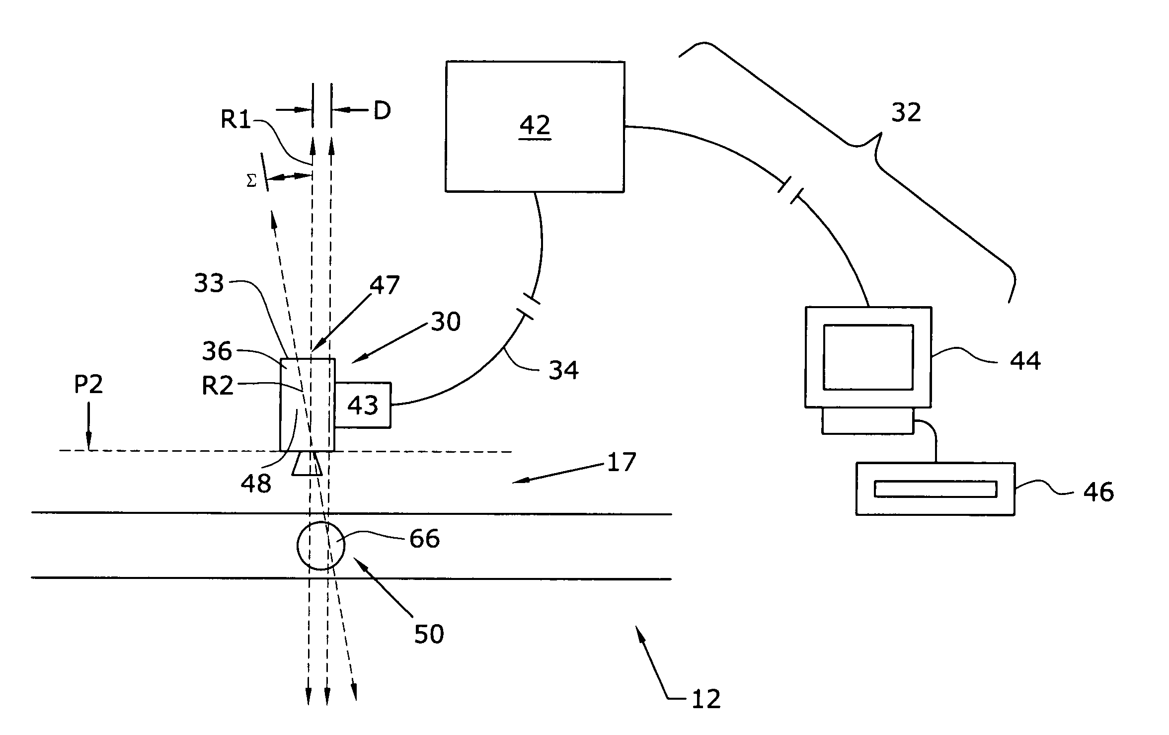
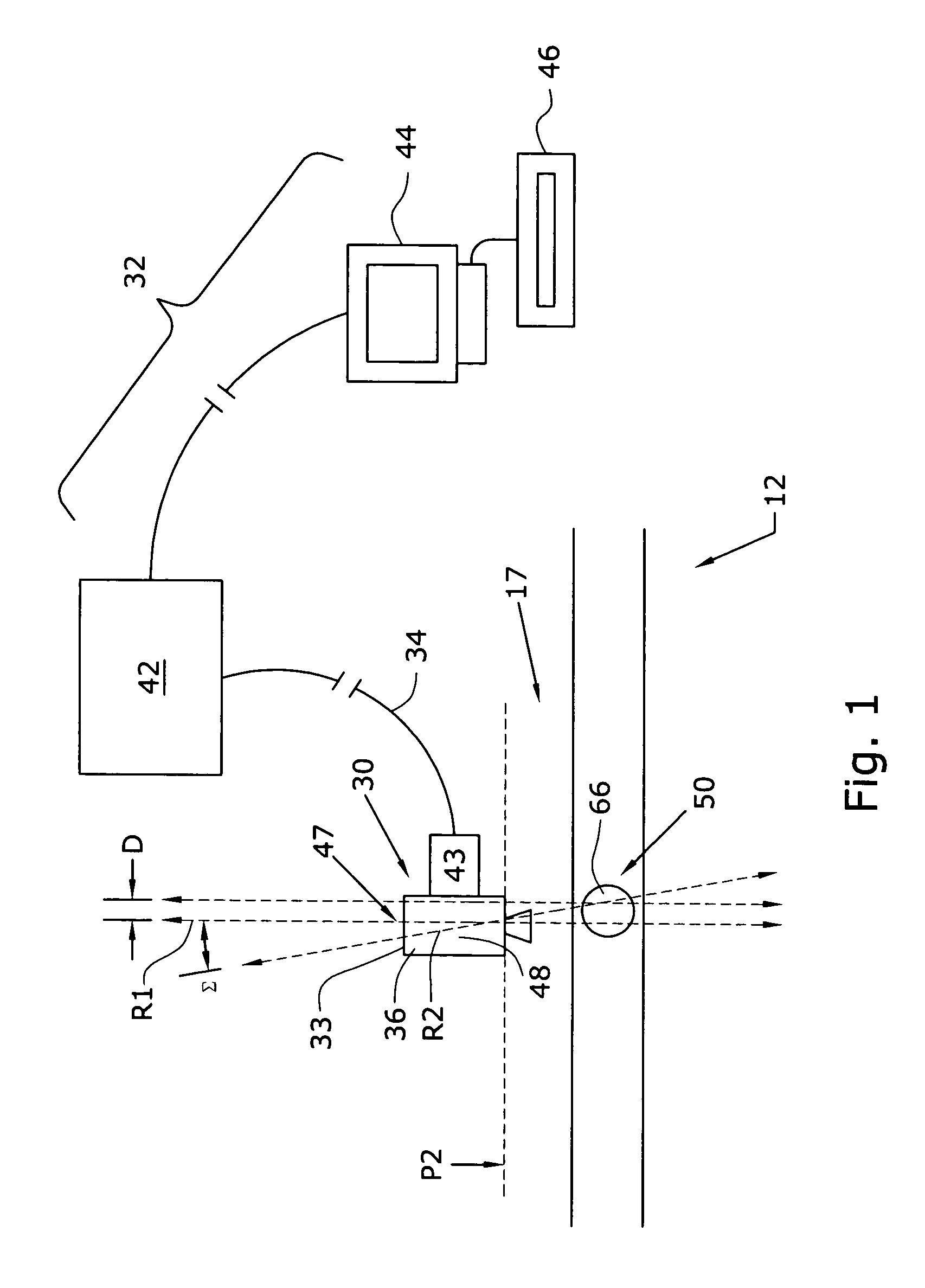
[0029]As illustrated in the accompanying drawings and discussed in detail below, one aspect of the present invention is directed to a method of calibrating a line scan vision detector or camera in a golf ball inspection system. First, a calibration object that mimics a golf ball is positioned on a golf ball production line at an inspection station. Then, the inspection camera images the calibration object. Next, the calibration object image is compared with an ideal image. Finally, the spatial and focal positioning of the detector with respect to the calibration object is adjusted to minimize differences between the calibration object image and the ideal image. By adjusting the detector with respect to the calibration object, the detector is thereby calibrated to accurately inspect golf balls using images that have minimal distortion.

[0030]An illustrative detection system to which this method can be applied is shown in FIG. 1. Golf ball production comprises several steps, and each s...


PUM

PropertyMeasurementUnit
distanceaaaaaaaaaa
angleaaaaaaaaaa
speedaaaaaaaaaa

Abstract

A method of calibrating a detector using a calibration object having a rounded surface and indicia is disclosed. The calibration object, when coupled with a detector and analyzer, assists in minimizing image distortion caused by misalignment of the detector relative to the calibration object. A calibration object is also disclosed.

Description

FIELD OF THE INVENTION[0001]This invention generally relates to a method of calibrating a detector and a calibration object. This invention more particularly relates to a method of calibrating a line scan camera detector to acquire an accurate image of a golf ball and a calibration sphere for the same.BACKGROUND OF THE INVENTION[0002]In recent years the inspection and analysis of goods that travel along conveyor, processing, manufacturing and assembly lines have become increasingly automated to match demands for greater production speed. Keeping up with such demands required quicker methods of performing quality control and quality assurance. Automated inspection systems perform a large portion of this work.[0003]One type of detector used in such systems is a line scan camera. A line scan camera is a type of camera detector that can very quickly capture a single row of pixels of an object. The object is typically rotated while being scanned. The individual rows of pixels can then be...

Claims


Application Information

Patent Timeline
Patent Type & Authority Patents(United States)
IPC IPC(8): G01D18/00G01B21/04G01N21/95G01N33/00G06T7/00
CPCG01B21/042G06T7/0018G01N21/951G01N2033/008G06T7/80
Inventor FURZE, PAUL A.LAPRADE, DONALD
Owner ACUSHNET CO
Why Eureka
Try Eureka