
Pre-stressing sheath

Inactive Publication Date: 2006-06-06
COOGAN DONALD B
View PDF22 Cites 10 Cited by
  • Summary
  • Abstract
  • Description
  • Claims
  • Application Information

AI Technical Summary

Benefits of technology

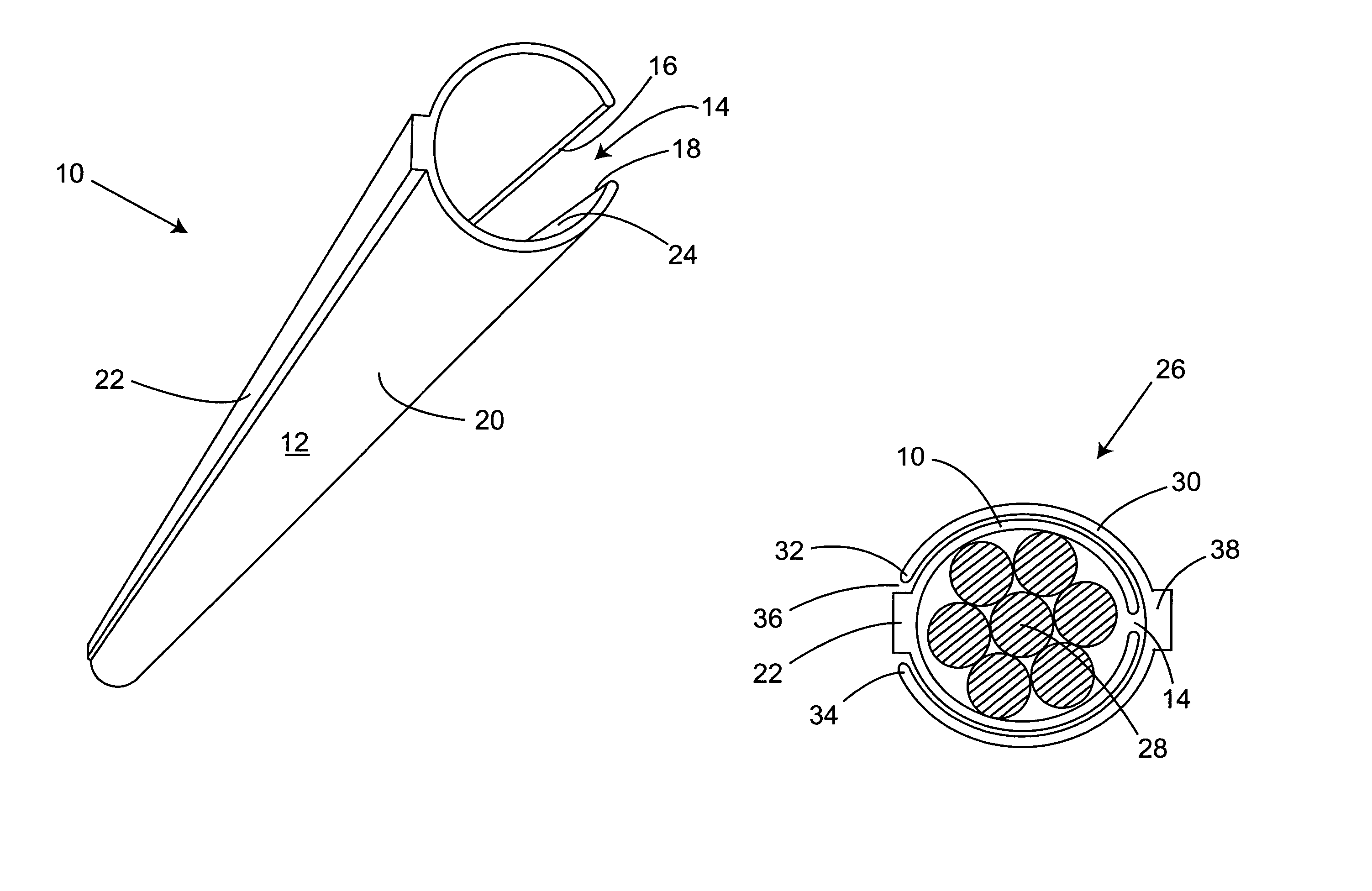
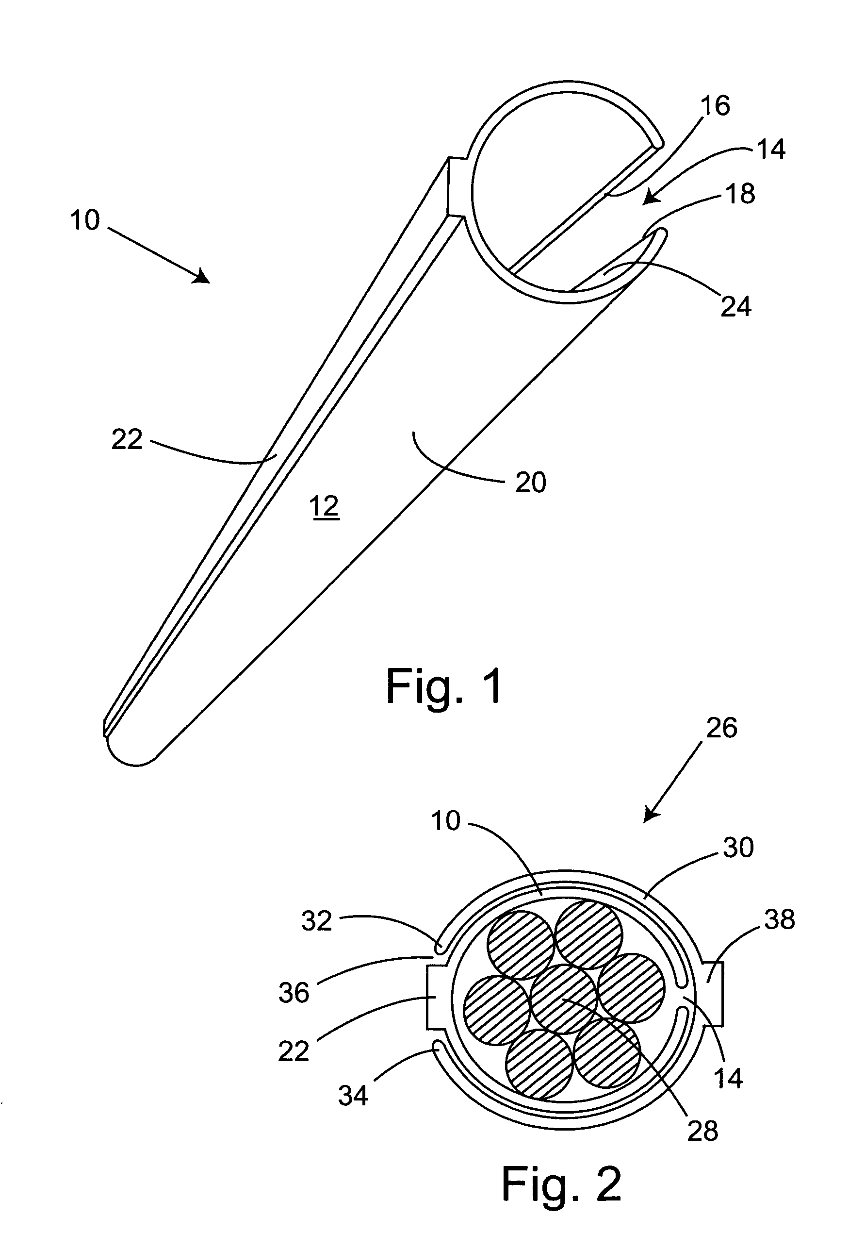
[0010]In use, a first sheath section is opened along its longitudinal slit just enough to be placed over a strand to be debonded. A second sheath section is opened along its longitudinal slit and is placed over both the strand and the first sheath section. The first and second sheath sections should be rotated about the enclosed strand relative to each other such that the longitudinal slit of the first sheath section does not coincide with the longitudinal slit of the second sheath section. Preferably, the longitudinal slits are positioned opposite to each other to maximize the seal protecting the strands from wet mortar.
[0012]In a preferred embodiment, the first and second sheath sections are identical with one advantage being minimized manufacturing costs. Another advantage is that identical first and second sheath sections allow interchangeability. Therefore only one type of sheath section needs to be in inventory to complete any given sheathing task.

Problems solved by technology

The effort required to position and stress the draped strands is expensive, time consuming, difficult and dangerous.
However, because of the longitudinal slit, this type of sheath is not as protective in preventing wet mortar from coming into contact with the strands to be debonded.
Therefore, while the split debonding sheath is currently favored, it by itself does not offer an adequate strand debonding solution.
While a hollow cylinder having a continuous wall offers the best protection for preventing wet mortar from coming into contact with the strands, it is difficult and sometimes impossible to apply.

Method used


Image

  • Pre-stressing sheath
  • Pre-stressing sheath

Examples


Embodiment Construction

[0017]In the following description, terms such as horizontal, upright, vertical, above, below, beneath, and the like, are used solely for the purpose of clarity in illustrating the invention, and should not be taken as words of limitation. The drawings are for the purpose of illustrating the invention and are not intended to be to scale.

[0018]Referring to the drawings and first to FIG. 1, a sheath section 10 comprises a first hollow cylinder 12 having a longitudinal slit 14 bounded by longitudinal edges 16 and 18. Sheath section 10 has an outer surface 20 that includes an outwardly projecting ridge 22 for aligning with the longitudinal slit of a second sheath section. Outwardly projecting ridge 22, also serves as a reinforcing spine extending the length of sheath section 10. Preferably, ridge 20 is located directly opposite longitudinal slit 14. Sheath section 10 has an inside surface 24 that has an inside diameter or circumference sized to envelop over half the circumference of a c...


PUM


Abstract

A pre-stressing sheath for preventing wet concrete from penetrating between the sheath and strands being debonded, and for covering sections of reinforcing strands in pre-stressed concrete beams such that any potential strand tension transmitted to a beam is nullified by allowing the strands to slide freely within the pre-stressing sheath. The pre-stressing sheath is made up of a first hollow cylindrical sheath section having a longitudinal slit that allows the first sheath section to be opened and placed about the concrete reinforcing element, and a second hollow cylindrical sheath section having a longitudinal slit that allows the sheath section to be opened and placed about both the concrete reinforcing element and the first sheath section. The first sheath section further includes an integral outwardly projecting ridge for interlocking with the longitudinal slit of the second hollow cylindrical sheath section.

Description

BACKGROUND OF THE INVENTION[0001](1) Field of the Invention[0002]The present invention relates generally to a pre-stressing sheath for preventing wet concrete from penetrating between the sheath and strands being debonded. In particular, the present invention relates to plastic clip-on type sleeves used to encircle and debond concrete reinforcing members such as cables.[0003](2) Description of the Prior Art[0004]Pre-cast concrete construction elements such as bridge girders, etc., are stressed by placing tension on an elongated cylindrical rod or cable bundle having a generally circular cross-sectional area normally formed of twisted wires generally referred to as strands. Strands that are placed in a straight configuration near the bottom of a pre-stressed girder tend to overstress near the end of the girder at the moment of de-tensioning. In order to avoid this overstress, several strands are usually draped upwardly near each girder end to reduce the eccentricity of the force they...

Claims


Application Information

Patent Timeline
IPC IPC(8): E04B1/00E04C5/08E04C5/10
CPCE04C5/10
Inventor COOGAN, DONALD B.
Owner COOGAN DONALD B
Learn More