Foldable Post for Shelving Apparatus

Inactive Publication Date: 2017-07-27
TSAI FRANK
View PDF0 Cites 2 Cited by
  • Summary
  • Abstract
  • Description
  • Claims
  • Application Information

AI Technical Summary

Benefits of technology

The invention provides a foldable post for a shelving apparatus that can be easily assembled and disassembled. It is designed with pivotally coupled post members, or engaged with a tongue-and-groove system, to ensure rigidity. The post can also be locked up to secure its position. The invention is cost-effective and does not require any major modifications to the shelving apparatus. These technical effects make it an efficient and economical solution for providing a rigid configuration for the foldable post of the shelving apparatus.

Problems solved by technology

However, after the objects are loaded and supported by the shelving unit, the overall weight of the objects will exerted to the vertical posts via the supporting panel.
In addition, when one of the tubular connectors A3 is broken or damaged, the supporting panels cannot be securely coupled to the vertical posts any more.
Therefore, the material cost of the shelving unit will be substantially high and the size of the shelving unit will be enlarged.
However, due to the frictional engagement between the end portion of the post member B1 and the coupler B2, the user may not able to correctly insert the end portion of the post member B1 into the gap of the coupler B2.
It is unstable for the shelf structure when the end portion of the post member B1 cannot be fully inserted into the gap of the coupler B2.
The excessive inserting force of the end portion of the post member B1 will damage the structure of the coupler B2 and will enlarge the size of the gap thereof.
Furthermore, such shaped detachable connecting structure cannot solve the same problem of how to easily disassemble the shelving unit.
The overall structure of the shelving unit become wobble and unstable.
In addition, when one of the couplers B2 is lost or damaged, the post members B1 cannot be coupled end-to-end any more.

Method used


Image

  • Foldable Post for Shelving Apparatus
  • Foldable Post for Shelving Apparatus
  • Foldable Post for Shelving Apparatus

Examples


Embodiment Construction

[0029]The following description is disclosed to enable any person skilled in the art to make and use the present invention. Preferred embodiments are provided in the following description only as examples and modifications will be apparent to those skilled in the art. The general principles defined in the following description would be applied to other embodiments, alternatives, modifications, equivalents, and applications without departing from the spirit and scope of the present invention.

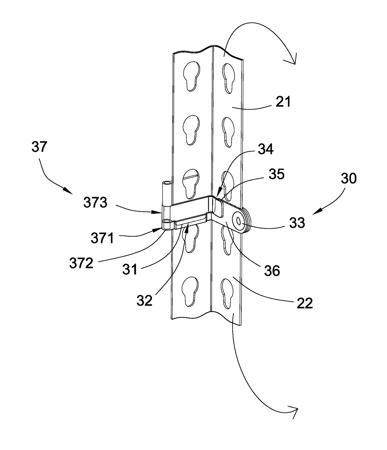
[0030]Referring to FIGS. 3 to 7, a shelving apparatus according to a preferred embodiment of the present invention is illustrated, wherein the shelving apparatus comprises a supporting frame 10, a plurality of foldable posts 20 for detachably coupling with the supporting frame 10, and a post joint 30.

[0031]According to the preferred embodiment, the supporting frame 10 is supported by the foldable posts 20 in a horizontally oriented manner for supporting one or more objects on the supporting frame...


PUM


Abstract

A foldable post for a shelving apparatus includes an upper post member, a lower post member, and a post joint for connecting the upper and lower post members end-to-end. The post joint includes an engaging tongue extended from an end portion of the first post wall of the upper post member, an engaging groove provided at an end portion of the first post wall of the lower post member, and a pivot hinge pivotally coupled the second post walls of the upper and lower post members, such that when the upper and lower post members are pivotally moved to engage the engaging tongue with the engaging groove, to the upper and lower post members are interlocked and coupled with each other end-to-end.

Description

NOTICE OF COPYRIGHT[0001]A portion of the disclosure of this patent document contains material which is subject to copyright protection. The copyright owner has no objection to any reproduction by anyone of the patent disclosure, as it appears in the United States Patent and Trademark Office patent files or records, but otherwise reserves all copyright rights whatsoever.BACKGROUND OF THE PRESENT INVENTION[0002]Field of Invention[0003]The present invention relates to a shelf structure, and more particularly to a foldable post for a shelving apparatus, wherein a plurality of post members of a foldable post can be easily assembled to rigidly support a plurality of supporting frames, and can be easily disassembled without detaching the post members.[0004]Description of Related Arts[0005]A conventional shelf structure comprises four vertical posts vertically extended from four corners of the shelf structure and a plurality of supporting panels horizontally and spacedly coupled at the ver...

Claims


Application Information

Patent Timeline
IPC IPC(8): A47B47/00A47B57/50
CPCA47B47/0083A47F5/101A47B2220/0072A47B45/00A47B47/021A47B87/02A47B87/0207A47B96/1458A47B43/00A47B96/145A47B87/0215A47B96/14A47B47/00A47F5/10A47B96/02A47B57/50F16B7/042F16B21/09A47B57/34F16B7/00
Inventor TSAI, FRANK
Owner TSAI FRANK
Why Eureka
Try Eureka