Objective lens driving device

a driving device and objective lens technology, applied in the direction of mountings, instruments, data recording, etc., can solve the problems of poor mechanical characteristics of the disk, inability to stably control the objective lens, and deterioration of the characteristics of the information recording, reproducing and erasing,

Inactive Publication Date: 2006-05-30
NEC CORP
View PDF6 Cites 8 Cited by
  • Summary
  • Abstract
  • Description
  • Claims
  • Application Information

AI Technical Summary

Benefits of technology

[0027]Another object of the present invention is to provide an objective lens driving device capable of realizing a stable tile control of the objective lens so as to obtain a good characteristics of information recording, reproducing and erasing, for an optical disk having a large surface swing or eccentricity of the optical disk medium, or for each of optical disks having different disk thicknesses thereby to have different optimum focal points, or even if the objective lens has been shifted in the tracking direction or in the focusing direction.
[0028]Still another object of the present invention is to provide an objective lens driving device having a minimized size in the radial direction and an increased accessible area for the optical disk.

Problems solved by technology

In addition, such disks having a poor mechanical characteristics which causes a large surface swing of the optical disk medium, or has a large eccentricity or tilt of the optical disk medium, start to appear with popularization of use of optical disks.
When the objective lens has been shifted in the tracking direction or in the focusing direction, the sensitivity and the linearity of the tilt movement change from those when the objective lens is in its neutral position, with the result that it is not possible to stably control the objective lens to a desired position, and therefore, the characteristics of the information recording, reproducing and erasing become deteriorated.
Furthermore, the objective lens driving device has a large size in the radial direction because the tilt coils provided at the side surfaces of the lens holder and the tilt magnets provided at the surfaces opposing the tilt coils, so that an accessible range to a center portion area of the optical disk medium is restricted, with the result that it is not possible to access an innermost recording area of the optical disk.

Method used


Image

  • Objective lens driving device
  • Objective lens driving device
  • Objective lens driving device

Examples


second embodiment

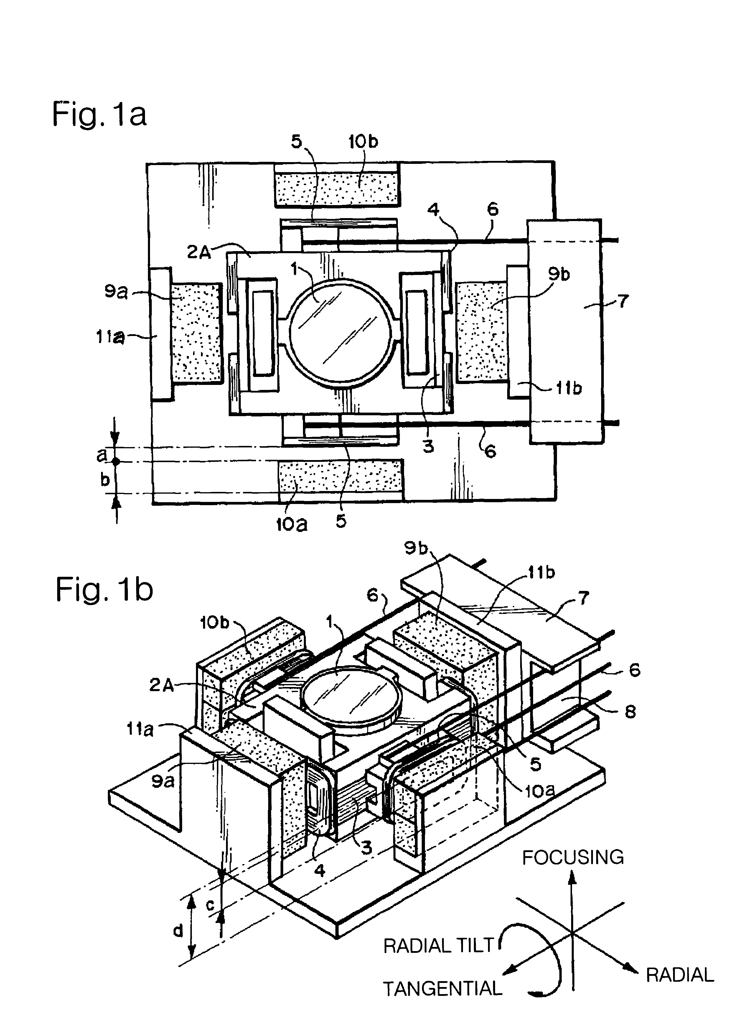
[0101]Now, the objective lens driving device in accordance with the present invention will be described with reference to FIGS. 8a and 8b. FIG. 8a is a plan view and FIG. 8b is a perspective view.

[0102]In order to thin objective lens driving device, this objective lens driving device is so configured that the objective lens 1 is located out of the magnetic circuit constituted of magnets 9a and 9b and yokes 11a and 11b for the focusing and the tracking. Thus, it is possible to locate an optical parts such a vertically guiding mirror, below the objective lens 1, whereby it is possible to thin the optical disk apparatus.

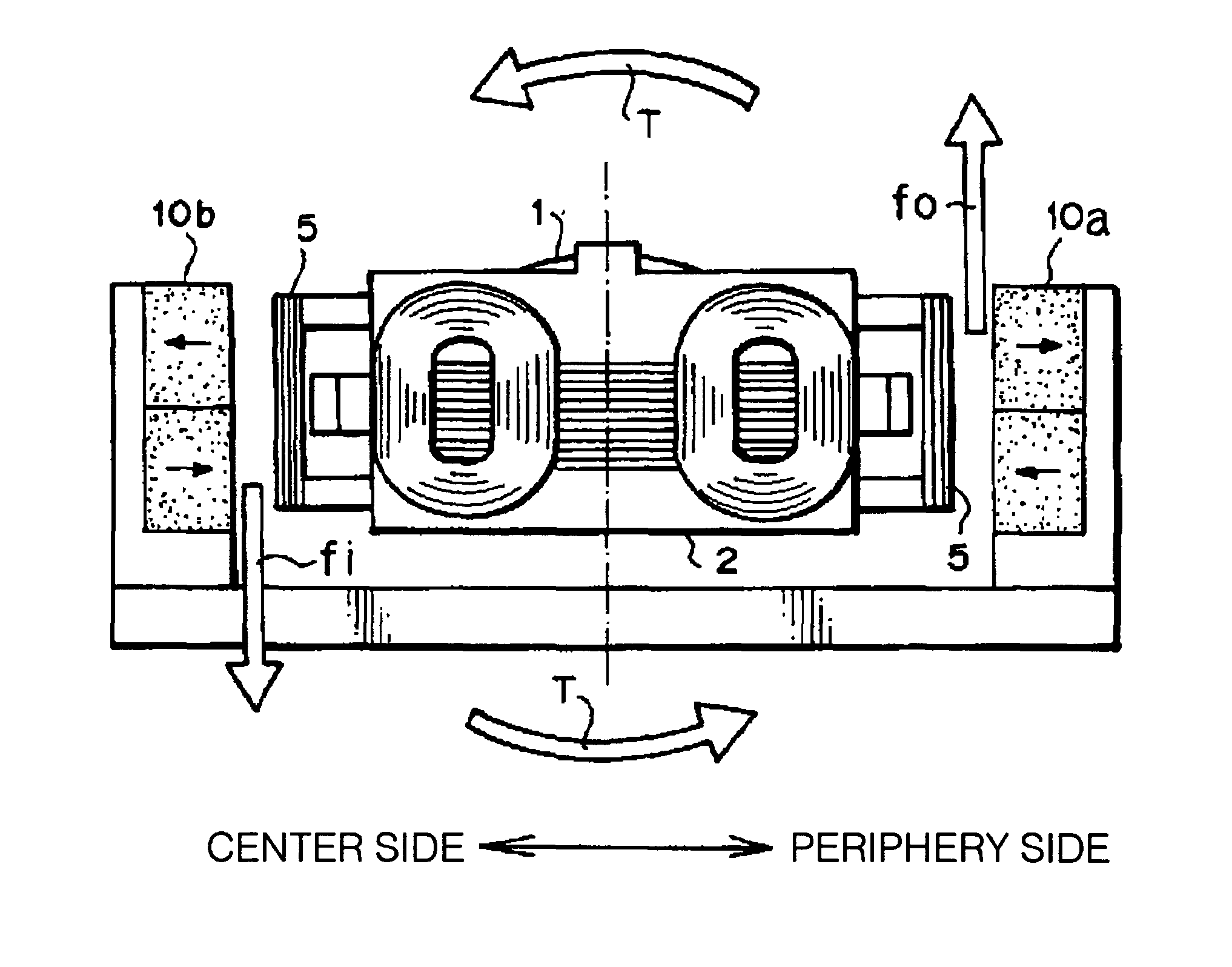
[0103]In this case, the tilt coils 5 are located at opposite sides of a lens holder 2B respectively, on an extension in the tangenial direction of the supporting member 6 fixed to lens holder 2B.

first embodiment

[0104]In this embodiment, similarly to the first embodiment mentioned above, the ratio of the distance between opposing surfaces of the tilt coils 5 and the tilt magnets 10a and 10b, namely, the gap “a” in FIG. 8a, to the radial direction thickness “b” of the tilt magnet 10a, is in the range of 1 / 3 to 1 / 2 when the lens holder 2B is held by the supporting member 6 in the condition of a substantially straight line. Namely, a / b is in the range of 1 / 3 to 1 / 2.

[0105]Furthermore, the ratio of the inside distance “c” in the focusing direction of an inner peripheral edge of a substantial rectangle or square where the tilt coil 5 starts to be wound, to the height “d” of the tilt magnets 10a and 10b is “d”, in the range of 1 / 2 to 1 / 4. Namely, the ratio of c / d is in the range of 1 / 2 to 1 / 4.

[0106]In addition, the tilt magnets 10a and 10b are formed of a rare earth material, and are magnetized to have two polarities at the surface opposing the tilt coil 5.

[0107]When the thinned objective lens dri...

third embodiment

[0109]Now, the objective lens driving device in accordance with the present invention will be described with reference to FIG. 11.

[0110]As shown in FIG. 11, a radial direction spacing “e” between mounting positions of the supporting members 6 to the lens holder 2A, is longer than a radial direction spacing “f” between mounting positions of the supporting members 6 to the fixed block 7.

[0111]FIG. 12 is a graph illustrating the relation between the primary resonance frequency in the tracking direction and the primary resonance frequency in the tilt direction, in relation to a difference between a radial direction spacing “e” of the mounting positions of the supporting member 6 to the lens holder 2A and a radial direction spacing “f” of the mounting positions of the supporting member to the fixed block.

[0112]In this case, the reference spacing of the spring wires is 8.6 mm, and the length of the spring wires is 10.6 mm.

[0113]As seen from FIG. 12, by comparing one case in which the diff...


PUM

PropertyMeasurementUnit
widthaaaaaaaaaa
heightaaaaaaaaaa
thicknessaaaaaaaaaa

Abstract

When a lens holder 2A is in a neutral position, a ratio of a gap between opposing surfaces of one tilt magnet 10a, 10b and one tilt coil 5 which oppose to each other, to a radial direction thickness of the tile magnet 10a, 10b, is in the range of 1 / 2 to 1 / 3. In at least one tilt coil of the tilt coils, a ratio of a light axis direction inside distance of the tilt coil to a light axis direction height of the tilt magnet, is in the range of 1 / 1.5 to 1 / 4. With this arrangement, even if the objective lens is shifted in a tracking direction or in a focusing direction, variation in the sensitivity and the linearity of the radial tilt movement is small, and an internally accessible area is increased.

Description

BACKGROUND OF THE INVENTION[0001]The present invention relates to an objective lens driving device for use in an optical disk apparatus, and more specifically to an objective lens driving device featured in location of a coil and a magnet which constitute a compensating mechanism for a tilt in a radial direction of an optical disk medium.[0002]Generally, in an optical disk apparatus, a laser light emitted from a light source typified by a semiconductor laser is condensed and irradiated onto an information recording surface of the optical disk medium in order to record, reproduce or erase information.[0003]In this optical disk medium, a track position in a recording surface on which the information is recorded, ceaselessly displaces in a focusing direction corresponding to a direction perpendicular to the plane of the optical disk medium and in a tracking direction corresponding to a radial direction of the optical disk medium, because of a surface swing and a eccentricity.[0004]Ther...

Claims


Application Information

Patent Timeline
Patent Type & Authority Patents(United States)
IPC IPC(8): G11B7/00G11B7/09G11B7/095
CPCG11B7/0932G11B7/0956G11B7/0935G11B7/0933
Inventor FUJITA, MASAYUKI
Owner NEC CORP
Why Eureka
Try Eureka