
General purpose distributed operating room control system

a control system and operating room technology, applied in the field of control systems, can solve the problems of reducing the efficiency of performing various procedures, cumbersome utilization, and no known run time configurable system for operating more than one specific operating room devi

Inactive Publication Date: 2006-05-30
INTUITIVE SURGICAL OPERATIONS INC
View PDF246 Cites 243 Cited by
  • Summary
  • Abstract
  • Description
  • Claims
  • Application Information

AI Technical Summary

Benefits of technology

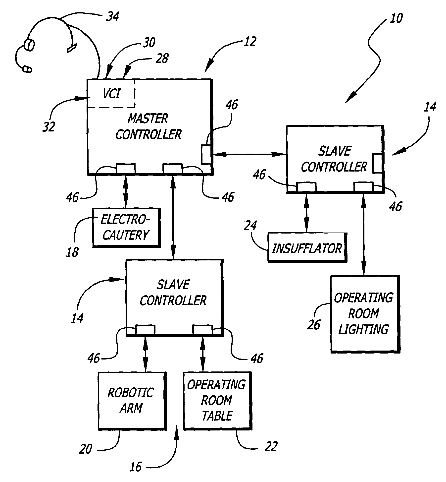
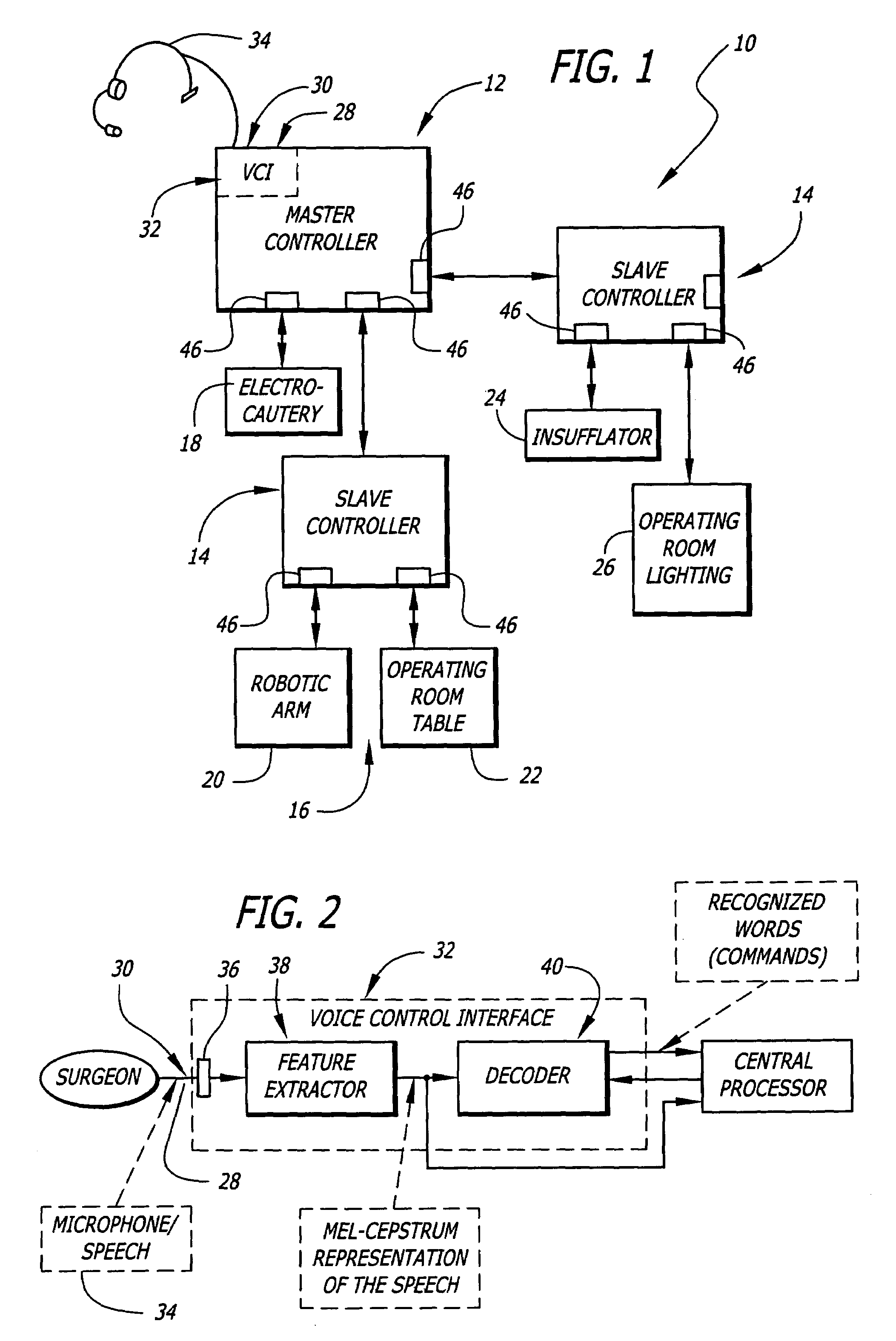
[0023]A second aspect of the present invention is at least one slave electrically connected to the master controller. Each slave controller connected to the master controller operates similarly to the master controller for specific devices electrically connected thereto; additionally, the slave controllers may receive control commands directly from the user if they are to be used as a stand alone unit. However, if they are utilized as slaves then control commands are received at the master controller and converted into control signals and transmitted from the master controller to the slave controller that has the device specified by the last selection command received by the master controller connected thereto. This allows the control system of the present invention to operate with a plurality of different devices without the master controller requiring any knowledge of the devices connected to the slave controllers prior to startup of the control system.

Problems solved by technology

Operating multiple devices may distract the surgeon, thereby reducing the efficiency of performing various procedures.
Additionally, it is cumbersome utilizing various devices where each device has a separate user interface.
Additionally, there is currently no known run time configurable system for operating more than one specific operating room device via voice control.
Obviously, this creates many problems associated with productivity.
Additionally, the necessity of actually switching between many user interfaces takes a measurable amount of time and as such, extends the time that a patient is under anesthesia, which may add to the danger of a procedure.

Method used


Image

  • General purpose distributed operating room control system
  • General purpose distributed operating room control system
  • General purpose distributed operating room control system

Examples


Embodiment Construction

[0033]In accordance with the present invention, there is shown in FIG. 1 an operating room control system, generally at 10, in accordance with the present invention. The operating room control system, or control system 10, generally comprises a master controller 12, which is preferably attached to at least one slave controller 14. Although the exemplary preferred embodiment is shown as having both a master controller 12 and at least one slave controller 14 in electrical communication therewith, the control system 10 may be implemented with only a master controller 12 as will be described hereinbelow.

[0034]The master controller 12 is electrically connected to and in electrical communication with a plurality of devices 16 via a plurality of communication ports 46. Alternatively, the master controller 12 may be connected to any slave or specific medical device via wireless communications systems such as IR or RF signal transmitters and receivers on each of the master 12, slaves 14, and...


PUM


Abstract

The present invention pertains to control systems and provides a run time configurable control system for selecting and operating one of a plurality of operating room devices from a single input source, the system comprising a master controller having a voice control interface and means for routing control signals. The system additionally may include a plurality of slave controllers to provide expandability of the system. Also, the system includes output means for generating messages to the user relating to the status of the control system in general and to the status of devices connected thereto.

Description

CROSS-REFERENCE TO RELATED APPLICATION[0001]This is a continuation patent application which claims priority from U.S. patent application Ser. No. 08 / 693,352 filed Aug. 6, 1996, now U.S. Pat. No. 6,646,541 the full disclosure of which is incorporated herein by reference.STATEMENT AS TO RIGHTS TO INVENTIONS MADE UNDER FEDERALLY SPONSORED RESEARCH OR DEVELOPMENT[0002]Not ApplicableREFERENCE TO A “SEQUENCE LISTING,” A TABLE, OR A COMPUTER PROGRAM LISTING APPENDIX SUBMITTED ON A COMPACT DISK.[0003]Not ApplicableBACKGROUND OF THE INVENTION[0004]1. Field of the Invention[0005]The present invention generally relates to control systems. More particularly, the present invention relates to a control system and apparatus that allows multiple surgical devices to be controlled from one or more input devices. Even more particularly, the present invention provides a run-time configurable control system allowing operating room component connectivity and control.[0006]2. Description of Related Art[00...

Claims


Application Information

Patent Timeline
IPC IPC(8): G05B23/02A61B17/00A61B19/00G05B15/02G10L15/26G16Z99/00
CPCA61B17/00A61B19/22G10L15/26G05B19/042G06F19/3406G06F19/3412G05B15/02A61B2017/00017A61B2017/00203G05B2219/23386A61B34/70G16H40/63G16H40/40G16Z99/00
Inventor WANG, YULUNJORDAN, CHARLES S.UECKER, DARRIN R.WOOTERS, CHARLES C.
Owner INTUITIVE SURGICAL OPERATIONS INC
Learn More