Split type NMR magnet device and NMR apparatus for solution analysis with at least an 11 T static magnetic field and different energizing directions of the NMR magnets

a technology of static magnetic field and magnet device, which is applied in the direction of measuring device, magnetic measurement, instruments, etc., can solve the problems of insufficient performance of conventional nmr apparatus, difficult to distinguish the interaction, and increased stability and uniformity, so as to improve the detection sensitivity, the effect of low solubility

Inactive Publication Date: 2006-05-30
HITACHI LTD
View PDF32 Cites 8 Cited by
  • Summary
  • Abstract
  • Description
  • Claims
  • Application Information

AI Technical Summary

Benefits of technology

[0018]To provide efficient, accurate analysis of the interactions of proteins with low molecular weight molecules, such as a substrate and ligand in a solution, for which the need will hereafter increase, it is desirable that the analysis be conducted by using an appropriate amount of sample with a frequency of 600 to 900 MHz and an intensity at the magnetic field center of about 14 to 21 T, and that the detection sensitivity and throughput be increased.
[0022]An object of the present invention is to provide a novel nuclear magnetic resonance analyzing apparatus in which the detection sensitivity of NMR signals is improved by 40% or more at a frequency of 600 MHz (14.1 T) with respect to the conventional apparatuses in a state where an ordinary sample tube having a diameter of 5 to 10 mm and containing a sample solution of 30 mm is placed therein, and in which a time stability and a space uniformity of the superconducting magnet required for protein analysis are provided. The present invention not be assumed to limit the operation temperature to 4.2 K in structure. It is possible to realize the ultimate performance through the application of the present invention; and, depending on the mode of the application, the apparatus of the present invention may be operated with the conventional upper limit magnetic field intensity of 21.1 T, i.e., 900 MHz and 1.8 K. In this case, the apparatus of the present invention is able to exhibit an improved sensitivity by 40% as compared with the conventional apparatuses, thereby advancing the upper limit of the detection sensitivity for the first time in the art.

Problems solved by technology

Further, if the magnetic field is non-uniform, desired peaks are overlapped to cause problems, such as difficulty in distinguishing the interaction.
Therefore, the performances of the conventional NMR apparatuses are insufficient, and the required stability and uniformity are greater than those achieved by the conventional NMR apparatuses by one digit or more.
Since the improvements in sensitivity of the conventional NMR apparatuses have been achieved by intensifying the magnetic field, the apparatuses have become too large.
Since a dedicated room was required for the apparatuses in view of the leakage magnetic field and the floor strength, problems such as poor installability have arisen.
Also, an increase in the cost of the superconducting magnet has been problematic.

Method used


Image

  • Split type NMR magnet device and NMR apparatus for solution analysis with at least an 11 T static magnetic field and different energizing directions of the NMR magnets
  • Split type NMR magnet device and NMR apparatus for solution analysis with at least an 11 T static magnetic field and different energizing directions of the NMR magnets
  • Split type NMR magnet device and NMR apparatus for solution analysis with at least an 11 T static magnetic field and different energizing directions of the NMR magnets

Examples


second embodiment

[0054]An arrangement of superconducting coils, according to the present invention, is shown in FIG. 2. Each of the pairs of (left and right) superconducting coils 11 to 16 and 11′ to 16′ (ex., the pair of 11 and 11′) is arranged so as to be substantially concentric with respect to a central axis extending along the horizontal direction. The left and right multilayer superconducting coils are arranged substantially symmetrically with respect to a center face extending along the vertical direction of the magnet device, and a certain distance is maintained between the centerline and each of the multilayer superconducting coils. The superconducting coils 14, 15, and 16 form the innermost layer, wherein the superconducting coils 15 and 15′ are energized in such a manner that the magnetic field generated thereby is in a direction reverse to that generated at the central part. Thus, a magnetic field of ppb-order uniformity is formed at the center portion of the split type magnet device of ...

third embodiment

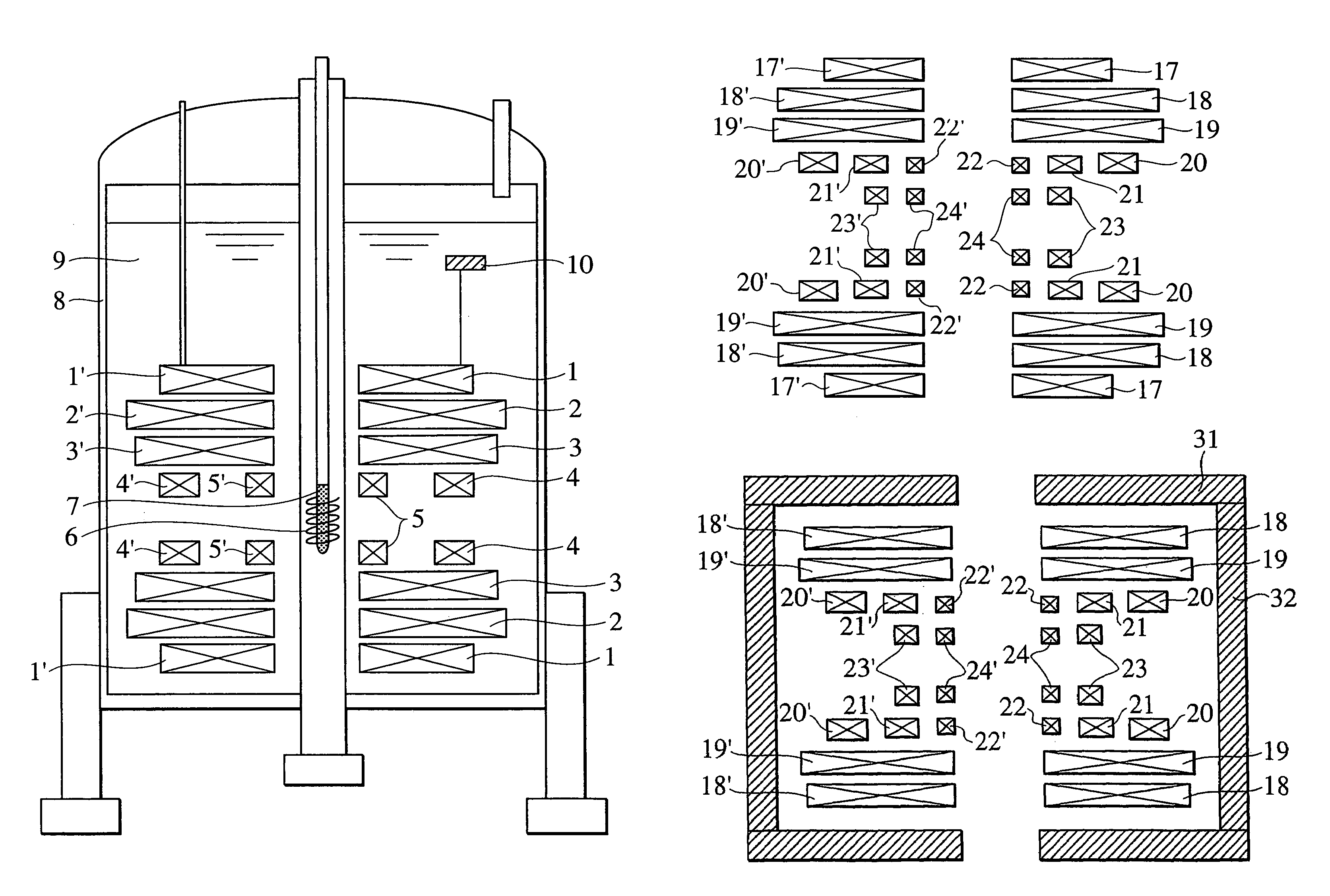
[0055]An arrangement of superconducting coils, according to the present invention, is shown in FIG. 3. Each of the pairs of (left and right) superconducting coils 17 to 24 and 17′ to 24′ (ex., the pair of 17 and 17′) is arranged substantially concentric with respect to a central axis extending along the horizontal direction. The left and right multilayer superconducting coils are arranged substantially symmetrically with respect to a center face extending along the vertical direction of the magnet device, and a certain distance is maintained between the center face and each of the multilayer superconducting coils. Among the layers formed by the pairs of (left and right) superconducting coils, the innermost layers are formed of the superconducting coils 23, 23′, 24 and 24′, and layers disposed radially outward from the innermost layers are formed of the superconducting coils 20, 20′, 21, 21′, 22 and 22′. The pair of superconducting coils 22 and 22′ and the pair of superconducting coi...

fourth embodiment

[0056]The NMR apparatus should desirably have a small leakage magnetic field; and, therefore, a fourth embodiment, which will described hereinafter, includes a shielding of the leakage magnetic field.

[0057]An arrangement of superconducting coils according to the fourth embodiment of the present invention is shown in FIG. 4. Superconducting coils 26 to 30 and 26′ to 30′ generate a uniform magnetic field at the center portion of the magnet device. In the present embodiment, the superconducting coil 30 and 30′ are energized to generate a magnetic field which is in a direction reverse to that generated by the other coils, so that a magnetic field of ppb-order uniformity is generated. Superconducting shielding coils 25 and 25′ are active shielding coils used for suppressing the leakage of the magnetic field.


PUM


Abstract

A split type magnet device configured for a high-sensitivity NMR apparatus and used for solution analysis generates a uniform magnetic field at the center portion of the magnet device of at least 11 T, which is used for determining a sample. The NMR magnet device has left and right solenoid superconducting magnets, which face each other with a predetermined distance being provided therebetween. The left solenoid superconducting magnets and the right solenoid superconducting magnets are substantially coaxial to a central axis, and constituted respectively by a plurality of outermost magnets and a separate plurality of innermost magnets. When a sample energizing current generates a main magnetic NMR detection field in the vicinity of a center portion of the apparatus the current direction in at least one of the plurality of innermost magnets is minus while the current direction in at least one of the plurality of outermost magnets is plus.

Description

CROSS REFERENCE TO RELATED APPLICATION[0001]This is a continuation of U.S. application Ser. No. 10 / 430,340, filed May 7, 2003 now ABANDONED, the contents of which are incorporated herein by reference.BACKGROUND OF THE INVENTION[0002]The present invention relates to a nuclear magnetic resonance analyzing apparatus; and, more particularly, the invention relates to a magnet device for generating a uniform magnetic field.[0003]Rapid progress has recently been made in the field of organic analysis using nuclear magnetic resonance. In particular, atomic structures of organic compounds, such as proteins, can now be efficiently analyzed by the combined use of nuclear magnetic resonance and superconducting ferromagnetic technology.[0004]An object of the present invention is to provide an NMR spectrometer which is necessary for analyzing atomic structures and interactions of protein molecules in a solution (the solution is prepared by dissolving minute amounts of proteins into a liquid). The ...

Claims


Application Information

Patent Timeline
Patent Type & Authority Patents(United States)
IPC IPC(8): G01V3/00G01R33/38G01R33/3815
CPCG01R33/3815G01R33/381
Inventor KAKUGAWA, SHIGERUOKADA, MICHIYAAIHARA, KATSUZOUMORITA, HIROSHIWAKUDA, TSUYOSHI
Owner HITACHI LTD
Why Eureka
Try Eureka