
Stepping motor with dual-layer bobbin cover

a bobbin cover and stepping motor technology, applied in the direction of horology, magnet circuit shape/form/construction, instruments, etc., can solve the problems of motor breakage, motor voltage drop, and motor breakage, so as to and improve the withstand voltag

Active Publication Date: 2006-05-30
MINEBEAMITSUMI INC
View PDF7 Cites 8 Cited by
  • Summary
  • Abstract
  • Description
  • Claims
  • Application Information

AI Technical Summary

Benefits of technology

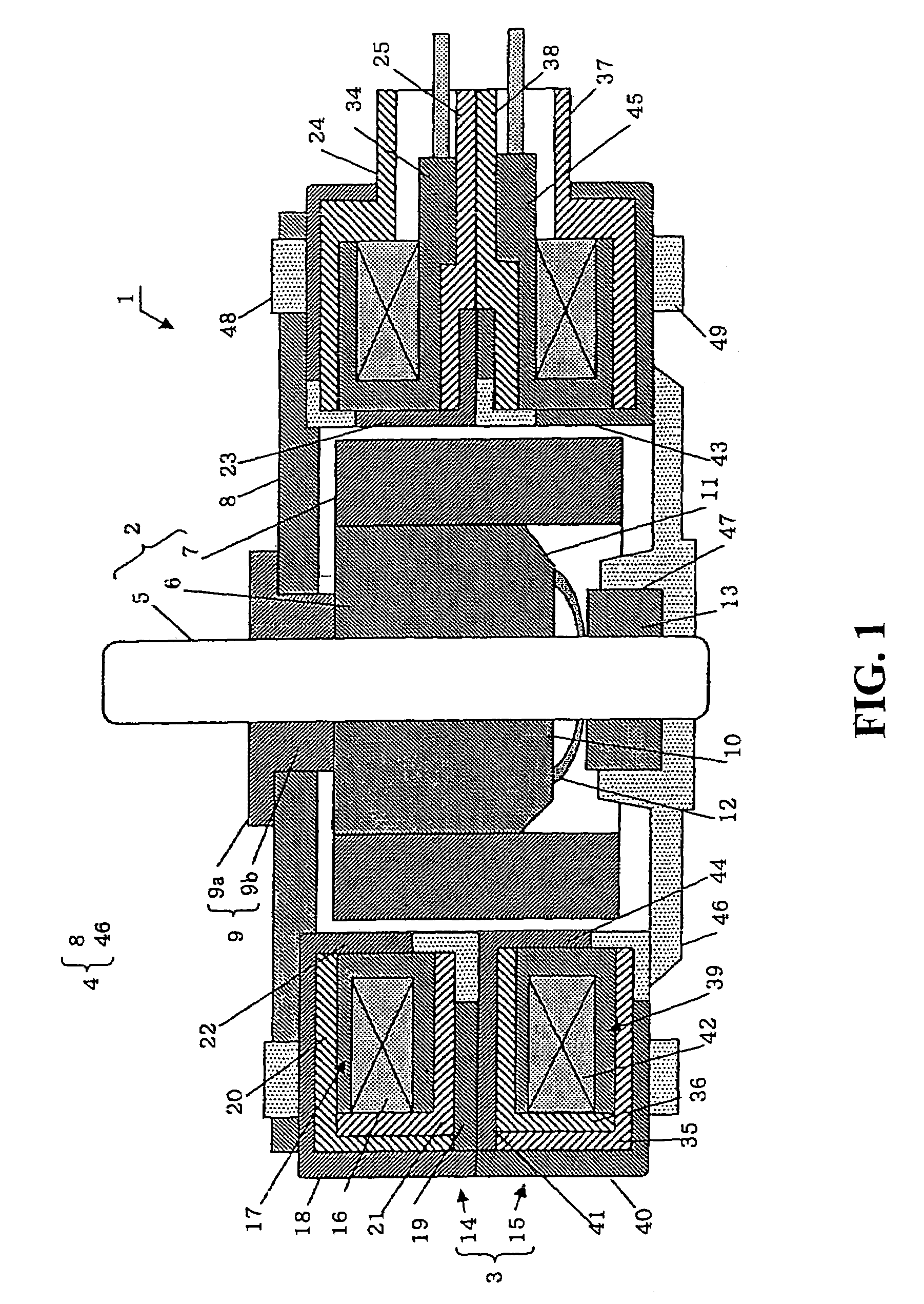
[0016]In order to achieve the object of the present invention, according to one aspect of the present invention, there is provide a stepping motor which comprises: a pair of stator yokes each having a plurality of pole teeth disposed in a comb-like arrangement; a bobbin disposed between the pair of stator yokes, the bobbin comprising a cylindrical body and two flanges (i.e., a first flange and a second flange), each of the two flanges radially extending outward from the cylindrical body so that the bobbin forms a squared U-shape in the axial cross-section thereof; a coil wound around the cylindrical body of the bobbin; and a bobbin cover case. In the stepping motor described above, the bobbin cover case comprises a dual-layer wall that covers an open mouth portion of the squared U-shape on the bobbin. Consequently, the bobbin cover case substantially inhibits a creepage discharge between the stator yokes and the coil, and a withstanding voltage is improved.
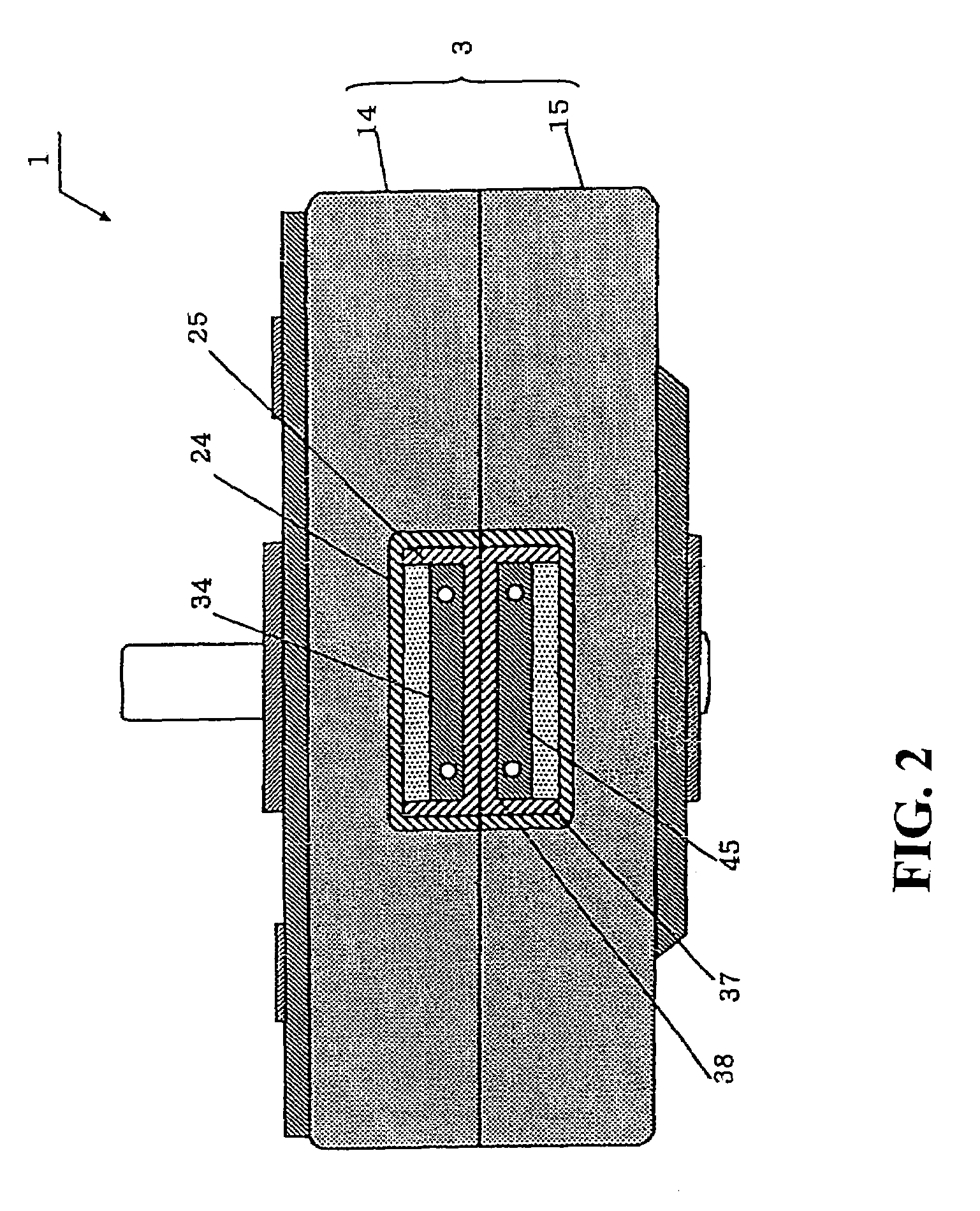
[0017]In the one aspect of the present invention, the bobbin cover case may be disposed between the stator yokes and the bobbin having the coil thereon, and the bobbin cover case may comprises an outer cover and an inner cover which are coupled to each other so as to cover the bobbin. The dual-layer wall may be an overlapping portion of the outer and inner covers, and the dual-layer wall may have a large axial dimension than the open mouth portion of the bobbin. The bobbin cover case may have a block portion extending beyond an outer circumference of the stator yokes so as to cover the terminal block of the bobbin. Preferably, the outer cover and the inner cover comprise a first block and a second block, respectively, which forms the block portion. Consequently, a creepage discharge between the stator yokes and the coil is inhibited, and a withstanding voltage therebetween is improved. Also, a creepage discharge between the stator yokes and the block portion is inhibited, and a withstand voltage therebetween is improved. Further, the bobbin and the bobbin cover case can be easily positioned to each other, and a withstand voltage is improved while ensuring a creepage distance within the block portion.

Problems solved by technology

Recently, the voltage of a power source for a motor used in a-household equipment is getting lower and lower, which renders the withstand voltage lower and lower.
As the withstand voltage gets lower, it happens more and more that motors break down due to a surge voltage from the power source.
While dielectric breakdown of a solid body is roughly classified into electronic breakdown, thermal breakdown, and electrical / mechanical breakdown, and is complicated, there are not so many practical methods of improving the withstand voltage, and a method of increasing the thickness of a layer to prevent the penetration of current, or a method of increasing the creepage distance of arc current may be used.
A PM stepping motor is mainly used in an audio visual equipment and office automation equipment, and therefore is requested to be downsized, which makes it difficult to ensure sufficient spatial clearance and creepage distance between a coil and stator yokes thus resulting in providing a withstand voltage of at most 1,000 V. So, in order to meet requirements of a withstand voltage of 5,000 V as described above, the outer circumference or the whole of a coil is sealed with synthetic resin (refer to, for example, Japanese Patent Application Laid-Open No.
This method of sealing with synthetic resin, however, requires time for curing the synthetic resin, which increases the production time resulting in a lowered productivity.
Also, since sealing with synthetic resin is an extra process for a typical PM stepping motor for use in an audio visual equipment or in an office automation equipment, the production control is complicated and the operation efficiency is worsened.

Method used


Image

  • Stepping motor with dual-layer bobbin cover
  • Stepping motor with dual-layer bobbin cover
  • Stepping motor with dual-layer bobbin cover

Examples


Embodiment Construction

[0025]The present invention will hereinafter be described with the accompanying drawings. Referring to FIG. 1, a stepping motor 1 according to the present invention comprises a rotor assembly 2 rotatably held, a stator assembly 3 to enclose the rotor assembly 2, and a case 4 to house the rotor assembly 2 and the stator assembly 3.

[0026]The rotor assembly 2 includes a rotary shaft 5, a rotor sleeve 6 shaped substantially cylindrical and fixed to the rotary shaft 5, and a permanent magnet 7 fixedly attached to the outer circumferential surface of the rotor sleeve 6. The outer circumference of the magnet 7 is magnetized alternately with S and N poles in the circumferential direction. One axial end (upper side in the figure) of the rotor sleeve 6 and the magnet 7 are flat, and continuous and flush with each other.

[0027]The other axial end (lower side in the figure) of the rotor sleeve 6 has a circular plane surface 10 at its central area and has an annular oblique (or inclined) surface ...


PUM


Abstract

In a stepping motor comprising a pair of stator yokes and a bobbin that includes a cylindrical body and two flanges, each of the two flanges radially extending outward from the cylindrical body so that the bobbin forms a squared U-shape in the axial cross-section thereof, there is provided a bobbin cover case disposed between the stator yokes and a coil wound around the bobbin, and the bobbin cover case includes an outer cover and an inner cover that are coupled to each other so as to provide a dual-layer insulating wall covering an open mouth portion of the squared U-shape, wherein the bobbin cover case inhibits a creeping discharge between the stator yokes and the coil.

Description

BACKGROUND OF THE INVENTION[0001]1. Field of the Invention[0002]The present invention relates to a stepping motor having an improved electrical insulating structure provided between a coil wound around a bobbin, and stator yokes to house the coil.[0003]2. Description of the Related Art[0004]Stepping motors, which are conveniently and well controllable, are used in various audio visual and office automation equipment. Especially, PM (permanent magnet) type stepping motors are extensively used also in various household equipment due to low cost.[0005]FIG. 5 is a partly cross-sectioned side view of a conventional PM stepping motor 100 (refer to, for example, Japanese Patent Application Laid-Open No. 2000-14118). The PM stepping motor 100 comprises a rotor assembly 101 rotatably held, a stator assembly 102 to enclose the rotor assembly 101, and casing 103 including a front plate 110 and a rear plate 111 and adapted to house the rotor assembly 101 and the stator assembly 102 together in ...

Claims


Application Information

Patent Timeline
Patent Type & Authority Patents(United States)
IPC IPC(8): H02K37/16H02K37/14H02K3/34H02K3/32H02K3/52H02K5/22H02K37/00
CPCH02K3/325H02K37/14H02K5/225H02K3/525
Inventor SUZUKI, YUZURU
Owner MINEBEAMITSUMI INC
Learn More