
System and method for camera calibration

a camera and system technology, applied in the field of cameras, can solve the problem of practicably impossible to obtain a set of single view images that fit together perfectly into a panorama, and achieve the effect of facilitating the exact alignment of images

Inactive Publication Date: 2006-05-23
IMMERSIVE LICENSING
View PDF55 Cites 56 Cited by
  • Summary
  • Abstract
  • Description
  • Claims
  • Application Information

AI Technical Summary

Benefits of technology

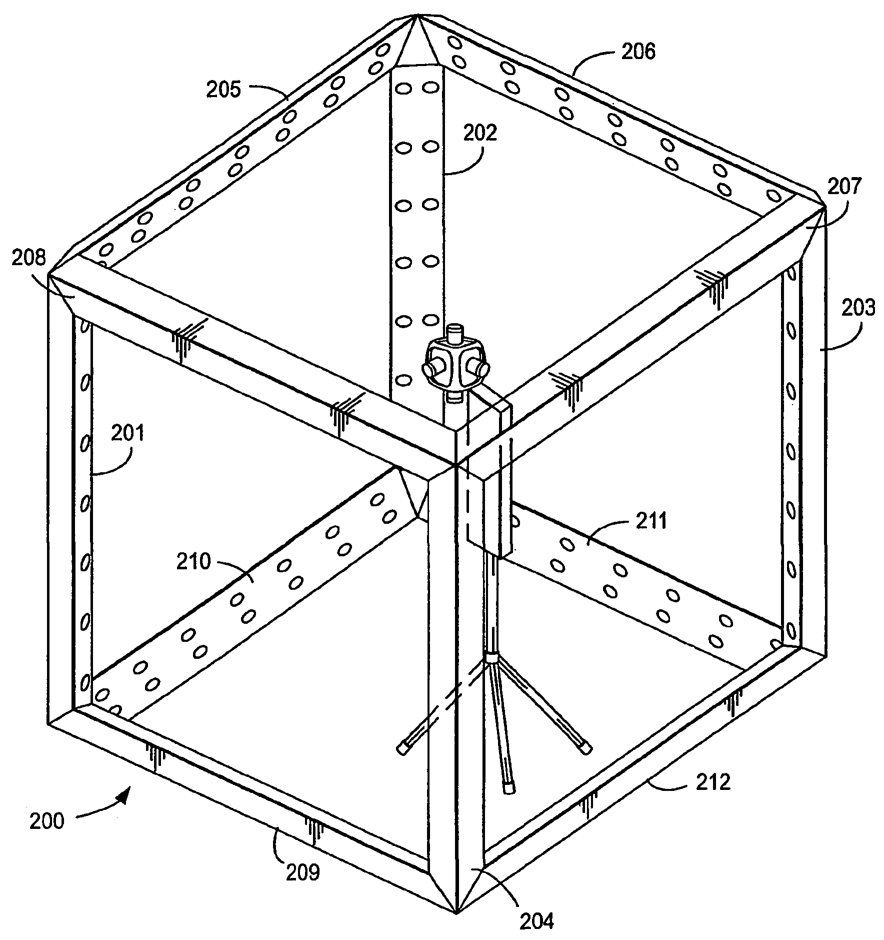
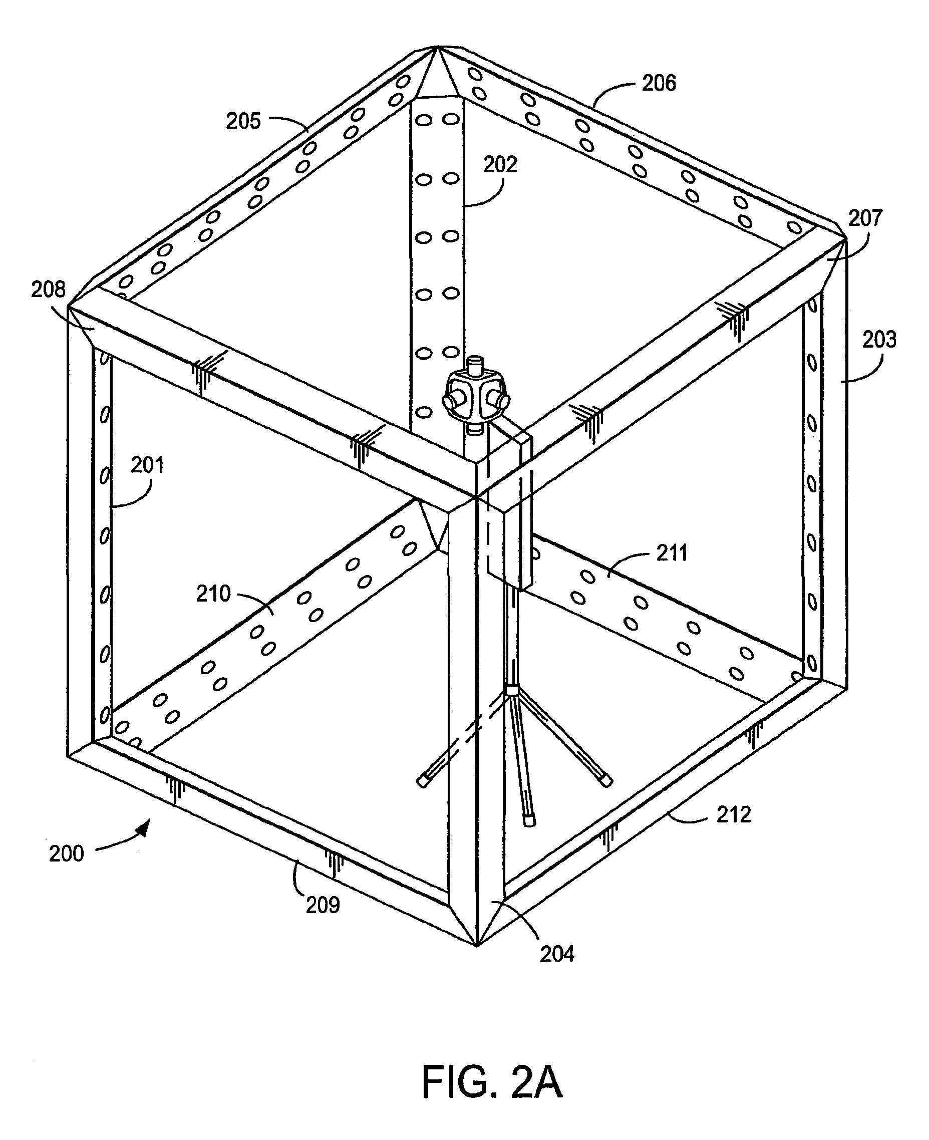
[0007]Another feature of the present invention includes providing two rows of indicia along the edges of the cube. The two rows of indicia are spaced apart by an amount equal to the distance between the lenses on the camera. This eliminates the need to correct for parallax and eliminates the need to position the camera at the exact center of the cube. Another feature of this invention is that the shape of the indicia is distorted so that when the indicia are recorded through a fisheye lens, the dots appear un-distored, thereby facilitating exact alignment of the images.

Problems solved by technology

It is practically impossible to obtain a set of single view images that fit together perfectly into a panorama.

Method used


Image

  • System and method for camera calibration
  • System and method for camera calibration
  • System and method for camera calibration

Examples


Embodiment Construction

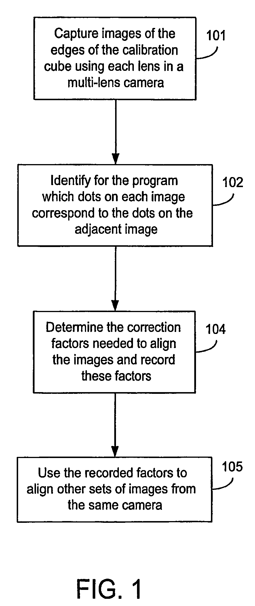
[0019]An overall flow diagram of the process performed by a preferred embodiment of the invention is shown in FIG. 1. The calibration structure used is shown in FIGS. 2A and 2B. The calibration structure 200 is cube shaped. First, as indicated by block 101 a particular camera 213 is used to capture images of the edges of the calibration cube 200. The images so captured can be termed calibration images.

[0020]The camera is a multi-lens camera with one lens pointing toward each side of the cube 200. A detailed description of camera 213 is given in co-pending application Ser. No. 09 / 338,790 filed Jun. 23, 1999 entitled “System for Digitally Capturing and Recording Panoramic Movies” the specification of which is hereby incorporated herein by reference. The camera 213 has six lenses and six images, one of each side of cube 200, are simultaneously recorded. Two lenses of camera 213 capture an image of each edge of the cube 200.

[0021]FIG. 3A shows an example of an image 331 captured by one ...


PUM


Abstract

A system and method for determining the adjustments that must be made to the individual images recorded by a multi-lens camera so that the images will fit together into a panorama. The camera is placed in the center of a structure, the edges of which have at least one row on indicia. Each camera records an image which includes the indicia along each edge that will be seamed with an edge of another image in order to form a panorama. Each edge of the structure which is along a seam that will be seamed with an edge of another image is recorded by two lenses on the camera. The amount of adjustment required to make the indicia in the two images fit together is then determined. The values of these adjustments are recorded along with an identification of the camera which recorded the images. Subsequent sets of images recorded by this same camera can then be seamed using the same adjustments.

Description

APPENDIX ON A CD[0001]Attached to this application is a CD (i.e. a compact disk) that includes text files (that is, an octal dump) of the programs listed below plus several text files.a) A calibration program used to determine the parameters needed to seam images.b) A seaming program which will seam images using the parameters determined by the calibration program.c) Text files with a copyright notice, operating instructions and an example of camera calibration parameters.FIELD OF THE INVENTION[0002]The present invention relates to cameras and more particularly to a system and method for determining the characteristics of cameras.BACKGROUND OF THE INVENTION[0003]Panoramic images can be created by seaming together multiple single view images. Multi lens cameras are available which can simultaneously capture multiple single view images. The images captured by such a camera can be subsequently seamed into a panoramic image. Patent application Ser. No. 09 / 602,290 filed Jun. 23, 2000 des...

Claims


Application Information

Patent Timeline
Patent Type & Authority Patents(United States)
IPC IPC(8): H04N7/00H04N5/225H04N7/18H04N17/00
CPCH04N5/23238H04N17/002H04N7/181H04N23/698
Inventor PARK, MICHAEL C.WILSON, SCOTT
Owner IMMERSIVE LICENSING
Learn More