
Integrated communication of building control system and fire safety system information

a technology for building control systems and information, applied in the field of data communication and/or display methods in building systems, can solve the problems of inability to conveniently review data from multiple systems in a contemporaneous manner, the cost of maintaining and using separate dedicated computer hardware and software, and the difficulty of reviewing fire safety system data and hvac data

Active Publication Date: 2006-05-23
SIEMENS IND INC
View PDF4 Cites 22 Cited by
  • Summary
  • Abstract
  • Description
  • Claims
  • Application Information

AI Technical Summary

Benefits of technology

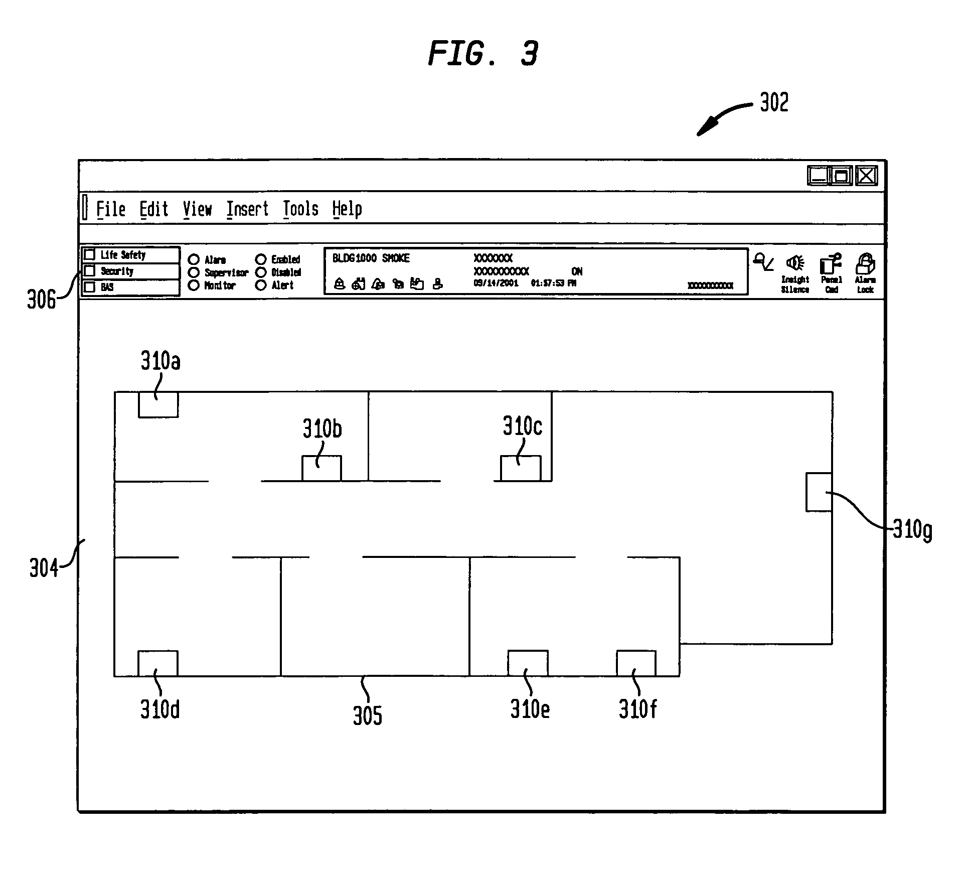
[0017]Embodiments of the present invention address the above needs, as well as others, by providing an alarm graphic element on a display concurrent with, and independent of, other graphic information on the display. The other graphic information may change (for example, in response to a user request), but such change would not change affect the display of the alarm graphic element. Thus, the alarm graphic element may be used to provide alarm or eve...

Problems solved by technology

One drawback of the use of separate isolated building systems is the cost associated with maintaining and using separate dedicated computer hardware and software.
Another drawback is the inability to conveniently review data from multiple systems in a contemporaneous manner.
If the operator must move between several workstations, possibly in different rooms or stations, then the review of fire safety system data and HVAC data is difficult.
Still another drawback is the complexity associated with using interfaces with several unrelated systems.
These fire safety conventions do not apply to other systems such as HVAC systems, and do not account for the types of data monitoring and control required of other systems.
Another drawback of building system interfaces relates specifically to the manner in which alarm is displayed.
In particular, the use of such a system can become cumbersome when multiple alarms are received from multiple devices for the same event.

Method used


Image

  • Integrated communication of building control system and fire safety system information
  • Integrated communication of building control system and fire safety system information
  • Integrated communication of building control system and fire safety system information

Examples


Embodiment Construction

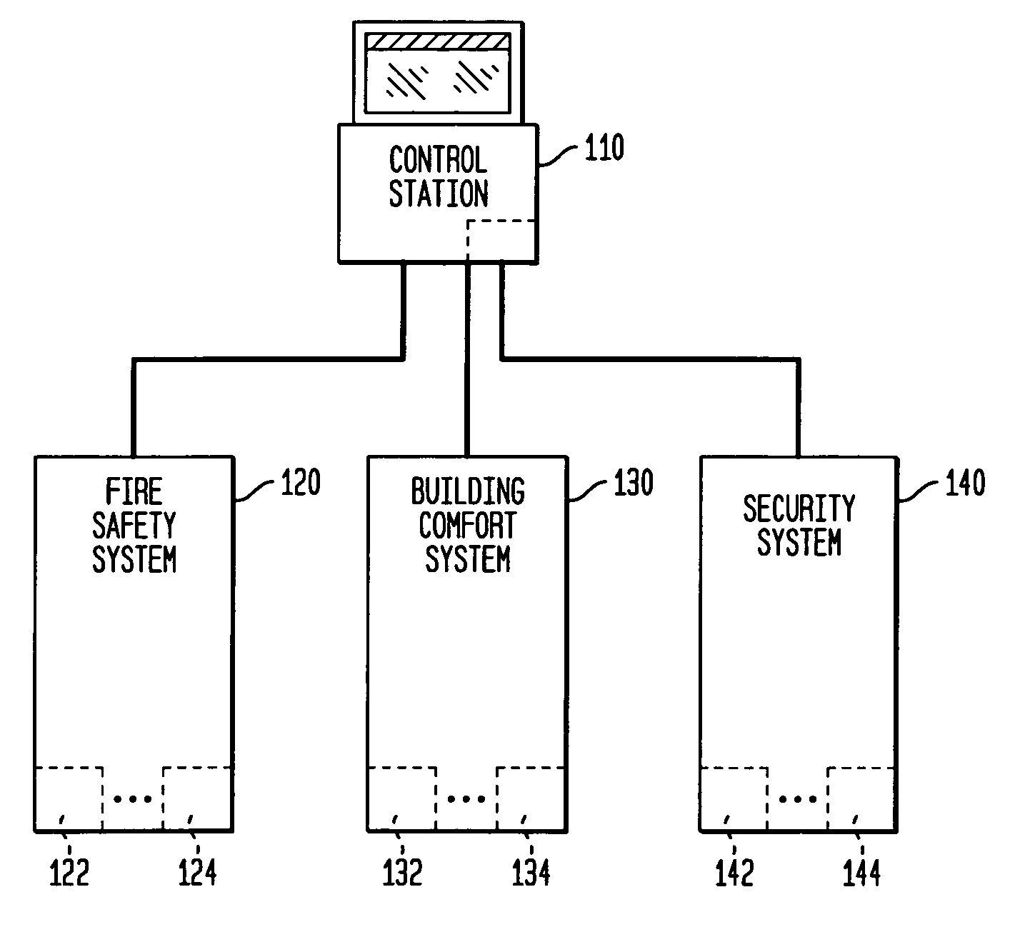
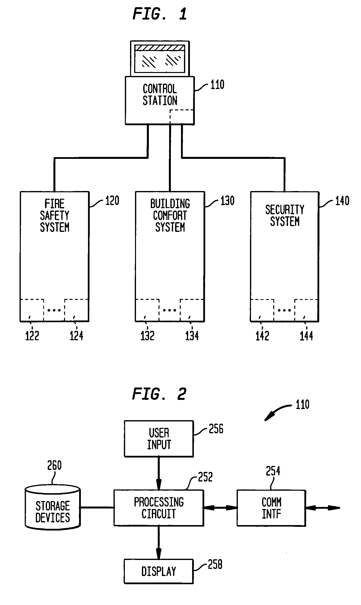
[0030]FIG. 1 shows a block diagram of an exemplary arrangement 100 for generating and obtaining alarm and other event information from a plurality of building systems 100. The arrangement includes a control station 110, a fire safety system 120, a building automation system 130, and a building security system 140.

[0031]The fire safety system 120 is an integrated system that includes a plurality of fire system devices (e.g. 122, 124) that perform any of a number of fire safety system functions. These functions may include smoke detection, fire detection, audible and visible notification of alarms, local control and communication, and others known in the art. The fire alarm system 120 is operable to perform the detection and notification functions normally associated with fire alarm systems. As one of the functions, the fire safety devices (including devices 122 and 124) are operable to communicate event messages to the control station 110 over one or more communication networks. An e...


PUM


Abstract

An apparatus for displaying event information from a building system includes a display device coupled to a processing circuit. The processing circuit is operable to cause the display to display information regarding a building system in a first portion of the display, the information being selectable and changeable by a user. The processing circuit is further operable to cause the display to display, independent of the displayed information in the first portion, an alarm graphic element in a second portion of the display, the alarm graphic element including building system event information.

Description

[0001]This application claims the benefit of U.S. Provisional Patent Application Ser. No. 60 / 390,341, filed Jun. 20, 2002, which is incorporated herein by reference.CROSS-REFERENCE TO RELATED APPLICATIONS[0002]Cross-reference is made to application Ser. No. 10 / 434,491, filed on even date herewith, entitled “Alarm Graphic Editor With Automatic Update”, which is owned by the owner of the present application and incorporated herein by reference. Cross-reference is also made to application Ser. No. 10 / 434,388, filed on even date herewith, entitled “Smoke Detector Maintenance Indication Method and Apparatus”, which is owned by the owner of the present application and incorporated herein by reference.FIELD OF THE INVENTION[0003]The present invention relates generally to data communication and / or display methods in building systems, and more particularly, to data communication and / or display methods for fire safety system and other building control systems.BACKGROUND OF THE INVENTION[0004]...

Claims


Application Information

Patent Timeline
IPC IPC(8): G08B23/00G08B17/10G08B25/14
CPCG08B17/10G08B29/188G08B25/14
Inventor RHODES, NEILHAN, JAMESRULE, TOMFARAGOI, JOHN
Owner SIEMENS IND INC
Learn More