
Implant system and method for bulking tissue

a tissue and implant technology, applied in the field of implants, can solve the problems of high cost of acid blockers, long-term complications of using acid blockers, and high cost of procedures

Inactive Publication Date: 2006-05-23
BOSTON SCI SCIMED INC
View PDF52 Cites 22 Cited by
  • Summary
  • Abstract
  • Description
  • Claims
  • Application Information

AI Technical Summary

Benefits of technology

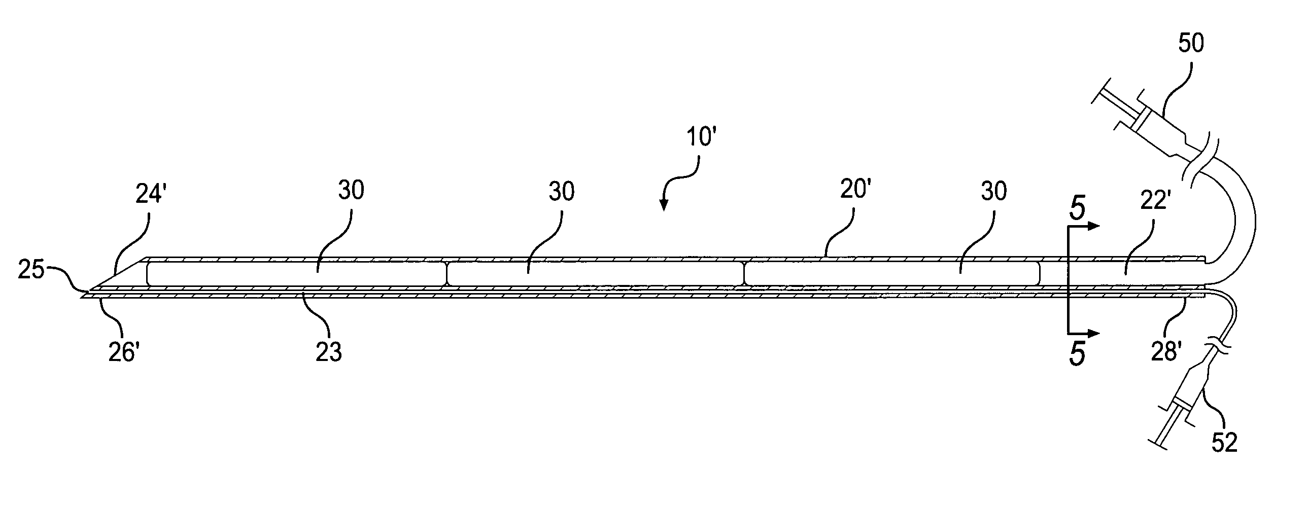
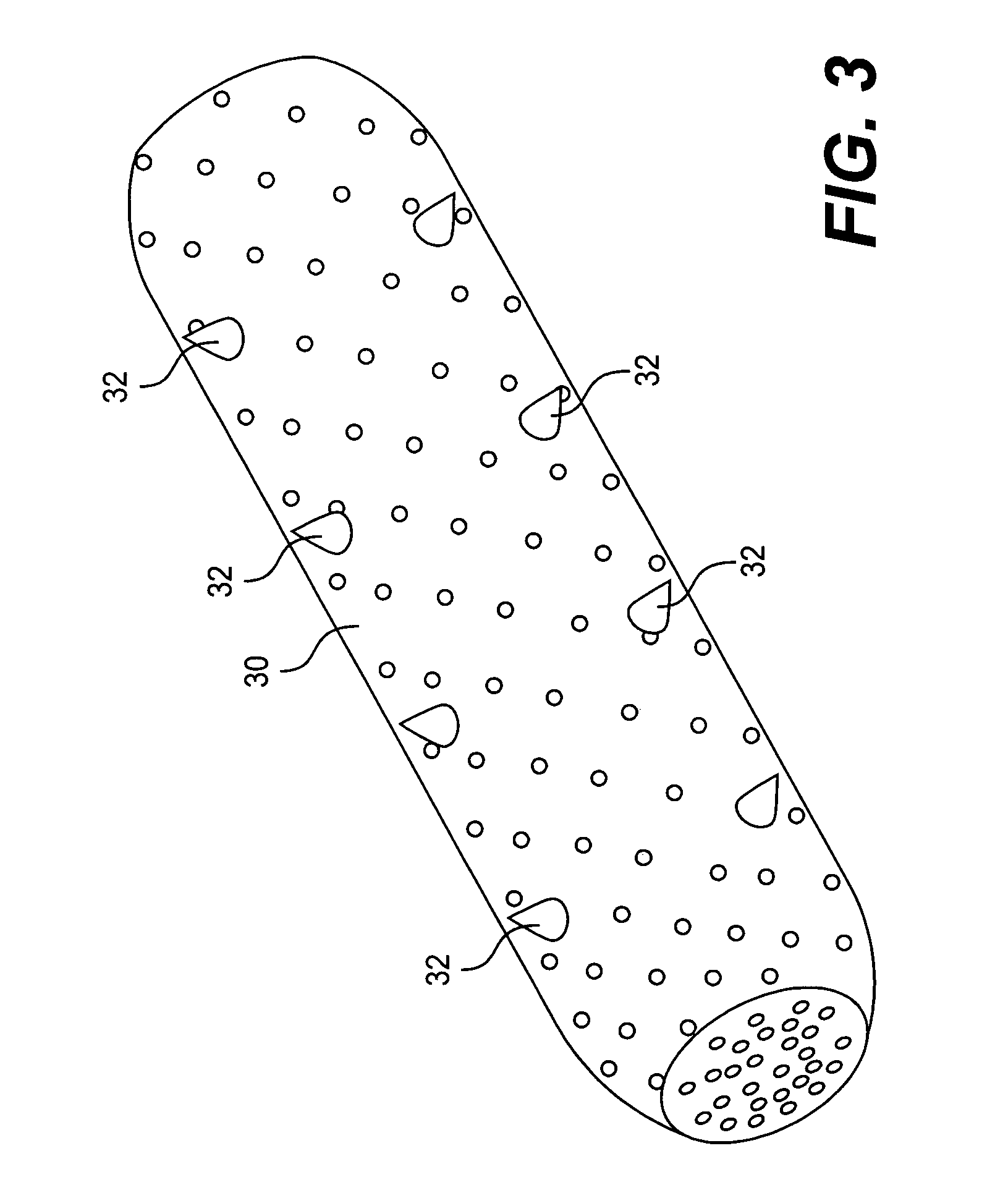
[0013]Accordingly, the present invention is directed to an implant, system and method that substantially obviate one or more of the limitations of the related art. To achieve these and other advantages and in accordance with the purpose of the invention, as embodied and broadly described herein, the invention includes a system for placing an implant in the body. The system comprises an elongated member and at least one compressible implant in an inner lumen of the member. The implant is configured to be implanted in body tissue to bulk the tissue. Structure is provided for pushing the implant through an opening in a distal end portion of the member.

Problems solved by technology

Although these drugs may provide short term relief, the drugs merely alleviate some of the symptoms of GERD rather than correcting the underlying dysfunction of the lower esophageal sphincter.
In addition, acid blockers are expensive, and any long term complications associated with using acid blockers are unknown.
However, such procedures are expensive and sometimes require a significant amount of time for patient recovery.
However, some of the relatively rigid stapling instruments used in these procedures may damage tissue when they are moved in a patient.
These abdominal wall penetrations increase the risks of post-operative hernias, accidental organ perforations, or other drawbacks associated with laparoscopic surgery.
Although the collagen could provide short term benefits, it eventually becomes absorbed by the body and loses it effectiveness.
However, the current implants and devices for inserting them have a number of disadvantages when they are used for tissue bulking.

Method used


Image

  • Implant system and method for bulking tissue
  • Implant system and method for bulking tissue
  • Implant system and method for bulking tissue

Examples


Embodiment Construction

[0045]Reference will now be made in detail to the present preferred embodiments of the invention, examples of which are illustrated in the accompanying drawings. Wherever possible, the same reference numbers are used in the drawings and the description to refer to the same or like parts, and similar reference numerals are used to refer to similar elements.

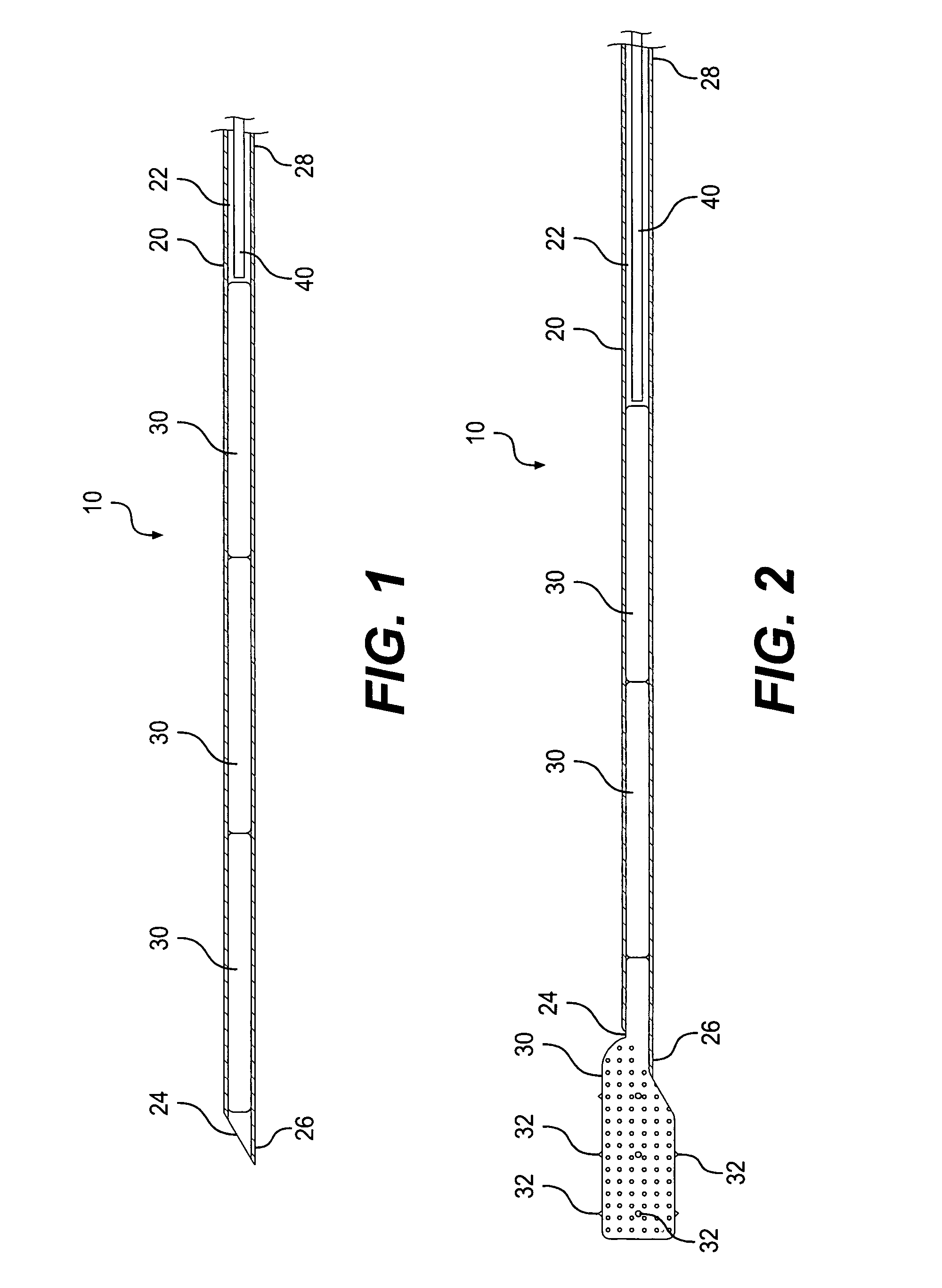
[0046]FIGS. 1 and 2 show an implant placement system 10 according to a first embodiment of the invention. As shown in FIGS. 1 and 2, the system 10 includes an elongated member 20 having an inner lumen 22, one or more implants 30 in the inner lumen 22, and a pushing member 40 for pushing the implants 30 through both the lumen 22 and an opening 24 in a distal end portion of the elongated member 20.

[0047]The elongated member 20 is preferably a hollow needle, cannula, or tubular member having a sharpened distal end 26 configured to pierce though layers of body tissue so that the opening 24 can be positioned between the tissue layers. W...


PUM


Abstract

A system for placing an implant in the body includes an elongated member having at least one inner lumen extending from a proximal end portion of the member to an opening in a distal end portion of the member. At least one compressible implant is in the inner lumen of the member. The implant optionally includes anchor members projecting from its outer surface to limit migration of the implant in the body. Structure is provided to push the implant through the opening in the distal end portion of the member. The implant is placed between layers of body tissue to bulk the tissue. In one of the disclosed methods, the system is used to treat gastroesophageal reflux disease (GERD) by placing the implant between layers of body tissue at or near the gastroesophageal junction.

Description

[0001]This is a continuation of application Ser. No. 09 / 110,125, filed Jul. 6, 1998, now U.S. Pat. No. 6,591,838.BACKGROUND OF THE INVENTION[0002]1. Field of the Invention[0003]The present invention relates to an implant and a system and method for placing the implant in the body to bulk body tissue. More particularly, the present invention relates to a system and method for placing the implant at or near the gastro-esophageal junction to treat gastroesophageal reflux disease (GERD).[0004]2. Description of Related Art[0005]The lower esophageal sphincter is located in a distal portion of the esophagus adjacent to the junction between the esophagus and the stomach. When food is digested, a properly functioning lower esophageal sphincter allows food to pass from the esophagus to the stomach while limiting reverse flow of the stomach contents into the esophagus.[0006]Gastroesophageal reflux disease (GERD) is a disorder in which the lower esophageal sphincter allows contents of the stoma...

Claims


Application Information

Patent Timeline
Patent Type & Authority Patents(United States)
IPC IPC(8): A61B19/00A61B17/00A61B17/34A61F2/00A61F2/20
CPCA61B17/00234A61B17/12022A61B17/3468A61F5/0079A61B2017/00557Y10S128/25A61F2/0036A61F2/20A61B2017/00827
Inventor DURGIN, RUSSELL
Owner BOSTON SCI SCIMED INC
Learn More