
Bessel free electron laser device

a laser device and electron beam technology, applied in the field of free electron lasers, can solve the problems of reducing optical gain, reducing peak power levels, and difficult process of matching e-beam and laser resonator beam for highly efficient conversion, so as to reduce peak power levels, enhance the optical gain of the system, and reduce peak power levels

Inactive Publication Date: 2006-05-16
THE BOEING CO
View PDF48 Cites 3 Cited by
  • Summary
  • Abstract
  • Description
  • Claims
  • Application Information

AI Technical Summary

Benefits of technology

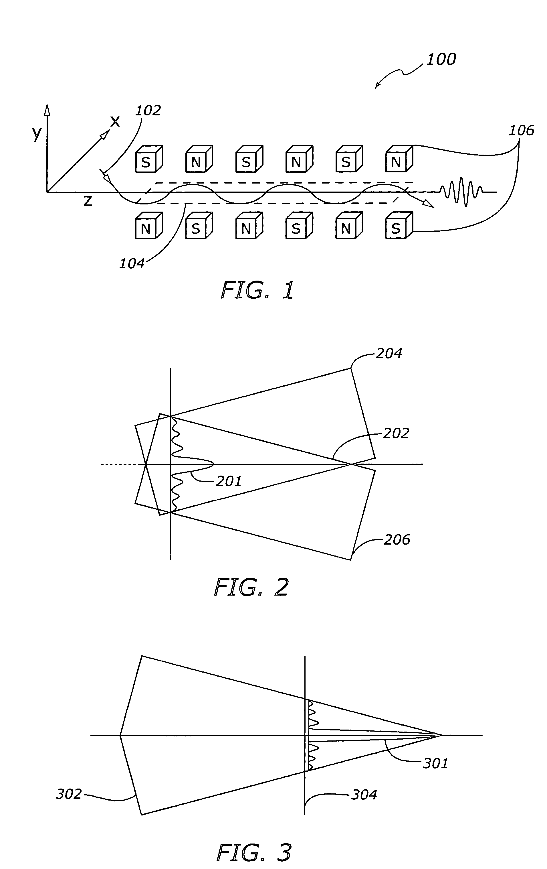
[0006]According to various exemplary embodiments, devices and methods are provided for propagating a laser beam with minimal divergence in a free electron laser (FEL). One exemplary method includes the steps of generating a relativistic electron beam, modifying the relativistic electron beam into a Bessel beam, and coupling the Bessel beam to the FEL optical field to produce a non-diverging laser beam. The non-diverging laser beam output can be shaped into a different beam pattern, such as a uniform intensity circular beam, for reducing peak power levels.
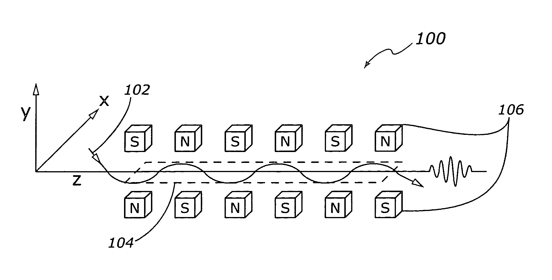
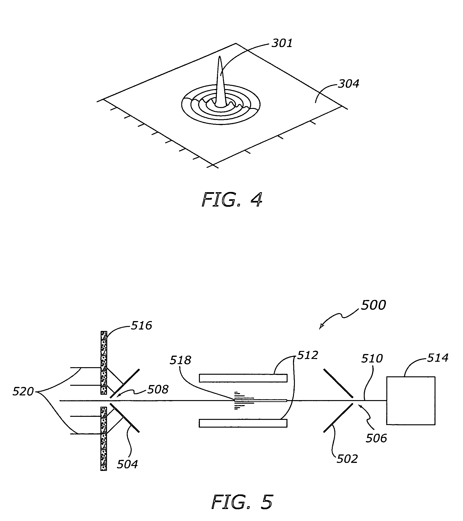
[0007]One exemplary device for propagating a non-diverging laser beam in an FEL includes an accelerator configured to generate a relativistic electron beam (e-beam) into a modified laser resonator. The laser resonator has conical mirrors at each end, with the conical mirrors facing each other. The mirrors each have beam apertures in their centers, with one mirror aperture configured to receive the e-beam from the accelerator, and the other mirror aperture configured to output the non-diverging laser beam. An array of magnets of alternating polarity, configured within the laser resonator, generate a transverse magnetic field. The interaction of the e-beam with the transverse magnetic field and with the conical end mirrors produces a Bessel beam, which is tightly coupled to the optical field within the laser resonator to produce a non-diverging laser beam output. The non-divergence characteristic of the beam in the resonator enables the use of a small gap in the magnet structure, which enhances the optical gain of the system. A wave front corrector can be positioned at the output of the laser resonator to shape the non-diverging laser beam into a uniform intensity circular beam to reduce peak power levels.

Problems solved by technology

As FEL devices are scaled up in power, however, the resonator end mirrors are typically subjected to very high power densities.
In addition, matching the e-beam and laser resonator beam for highly efficient conversion can be a difficult process.
The use of a small diameter laser beam, however, typically leads to an undesirable amount of beam divergence over the long electron beam interaction path generally needed for efficient amplification of the optical beam, with a corresponding reduction in optical gain.
Moreover, the use of a small diameter optical beam in an FEL generally results in very high power densities on the resonator mirrors that would typically limit the power capabilities of an FEL resonator with conventional mirrors.
However, the grazing incidence type of mirror design is generally very costly, due to the complexity of the mirror fabrication.

Method used


Image

  • Bessel free electron laser device
  • Bessel free electron laser device
  • Bessel free electron laser device

Examples


Embodiment Construction

[0014]The following detailed description is merely exemplary in nature and is not intended to limit the invention or the application and uses of the invention. Furthermore, there is no intention to be bound by any expressed or implied theory presented in the preceding technical field, background, brief summary or the following detailed description.

[0015]Various embodiments of the present invention pertain to the area of enhancing the power output capabilities of an FEL type device. One exemplary embodiment provides a modified laser resonator that shapes an e-beam into a Bessel beam configuration. The Bessel beam is coupled with the optical field in the resonator to produce a non-diverging laser beam, which allows for a smaller wiggler magnet gap and the associated higher optical gain. The use of a smaller laser beam diameter can also lead to a more rapid beam divergence at the end of the Bessel range, which enables the use of larger end mirrors to reduce the power density of the imp...


PUM


Abstract

Methods and apparatus are provided for modifying a free electron laser (FEL) to produce a non-diverging laser beam. A relativistic electron beam is converted to a Bessel beam in an FEL resonator with conical end mirrors, and the Bessel beam is coupled to the optical field within the laser resonator. The resultant laser beam is propagated with minimal divergence, and is wave corrected at the resonator output to produce a uniform intensity circular beam. The laser beam can be of smaller diameter than that of a conventional resonator due to its diffractionless propagation, which enables the magnetic structure gap within the resonator to be smaller, thus producing a higher optical gain.

Description

TECHNICAL FIELD[0001]The present invention generally relates to a Free Electron Laser (FEL), and more particularly relates to a Bessel beam FEL.BACKGROUND[0002]A Free Electron Laser (FEL) is a form of laser device invented by J. M. J. Madey in 1971. The FEL is a laser device in which the optical gain is provided by the motion of free electrons, as opposed to electrons that are bound to lasant ions, or are moving about in a semiconductor. In a typical FEL device, a laser beam propagates coaxially with a relativistic electron beam, or e-beam, in a resonator. The e-beam is generally a very high-energy beam, which is usually produced by an accelerator. The e-beam typically passes through a transverse periodic magnetic field produced by a regularly spaced array of magnets of alternating polarity. The magnet structure, known as an “undulator” or “wiggler magnet”, is designed to cause the e-beam to exchange energy with the transverse magnetic field. This energy interchange tends to generat...

Claims


Application Information

Patent Timeline
Patent Type & Authority Patents(United States)
IPC IPC(8): H01S3/00H01S3/09
CPCH01S3/0903
Inventor RICE, ROBERT R.
Owner THE BOEING CO
Learn More