Image-formation optical system, and imaging system
an image-formation optical system and imaging system technology, applied in the field of image-formation optical systems and imaging systems, can solve the problems of inability to achieve high performance, inability to achieve high-performance images, and inability to achieve high-quality images. achieve the effect of improving performan
- Summary
- Abstract
- Description
- Claims
- Application Information
AI Technical Summary
Benefits of technology
Problems solved by technology
Method used
Image

Examples
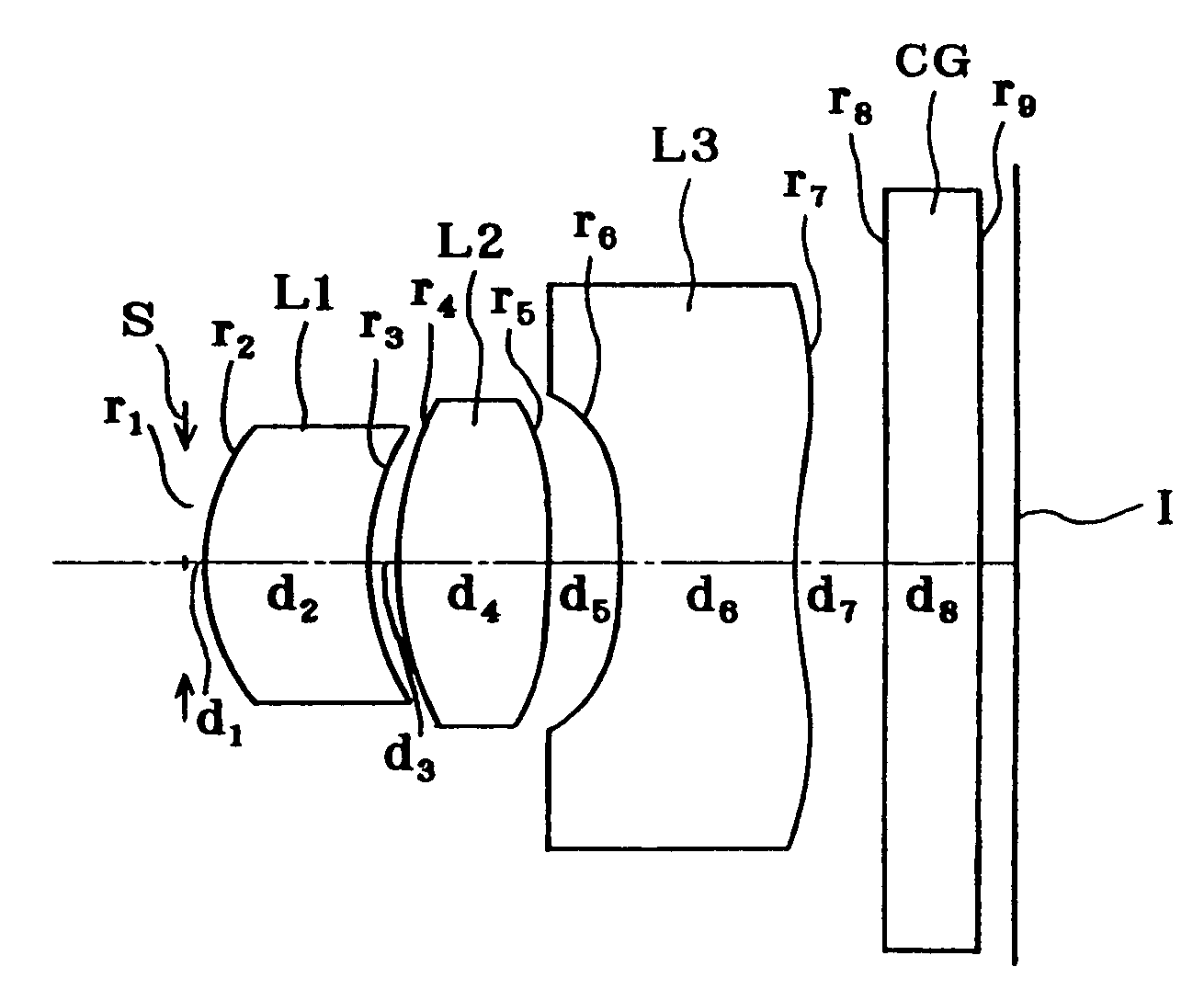
example 1
[0151]
r1 = ∞ (Stop)d1 = 0.10r2 = 1.365 (Aspheric)d2 = 0.63nd1 = 1.50913νd1 = 56.20r3 = 2.622d3 = 0.46r4 = 2.750d4 = 0.70nd2 = 4.50913νd2 = 56.20r5 =−47.775 (Aspheric)d5 = 0.60r6 = −5.474 (Aspheric)d6 = 0.62nd3 = 1.57268νd3 = 33.51r7 = 2.645 (Aspheric)d7 = 0.40r8 = ∞d8 = 0.50nd4 = 1.51633νd4 = 64.14r9 = ∞
Aspherical Coefficients[0152]2 nd surface[0153]K=−0.664[0154]A4=7.93801×10⁻³ [0155]A6=1.59402×10⁻² [0156]A8=−2.69710×10⁻³ [0157]5 th surface[0158]K=612.567[0159]A4=−2.69780×10⁻² [0160]A6=−1.22057×10⁻² [0161]A8=4.19450×10⁻² [0162]6 th surface[0163]K=−43.850[0164]A4=−4.22561×10⁻¹ [0165]A6=−5.25463×10⁻² [0166]A8=−7.90009×10⁻² [0167]7 th surface[0168]K=0.000[0169]A4=−2.59494×10⁻¹ [0170]A6=5.15201×10⁻² [0171]A8=−4.92327×10⁻³
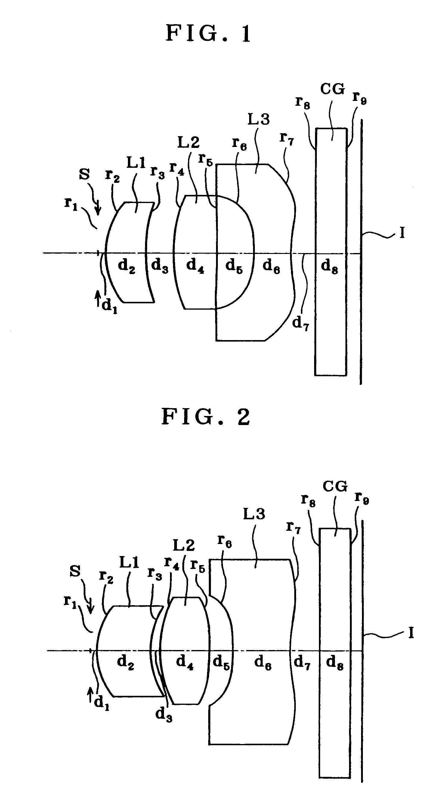
example 2
[0172]
r1 = ∞ (Stop)d1 = 0.10r2 = 1.313 (Aspheric)d2 = 0.84nd1 = 1.50913νd1 = 56.20r3 = 1.488d3 = 0.14r4 = 2.106d4 = 0.80nd2 = 1.50913νd2 = 56.20r5 = −5.751 (Aspheric)d5 = 0.38r6 =−11.293 (Aspheric)d6 = 0.93nd3 = 1.57268νd3 = 33.51r7 = 2.159 (Aspheric)d7 = 0.50r8 = ∞d8 = 0.50nd4 = 1.51633νd4 = 64.14r9 = ∞
Aspherical Coefficients[0173]2 nd surface[0174]K=0.000[0175]A4=−3.44484×10⁻² [0176]A6=−5.44446×10⁻⁵ [0177]A8=0[0178]5 th surface[0179]K=4.258[0180]A4=−1.33824×10⁻¹ [0181]A6=4.38330×10⁻² [0182]A8=0[0183]6 th surface[0184]K=0.000[0185]A4=−3.99293×10⁻¹ [0186]A6=2.75894×10⁻² [0187]A8=−5.61639×10⁻² [0188]7 th surface[0189]K=−16.238[0190]A4=−7.90754×10⁻² [0191]A6=1.64359×10⁻² [0192]A8=−1.28594×10⁻³
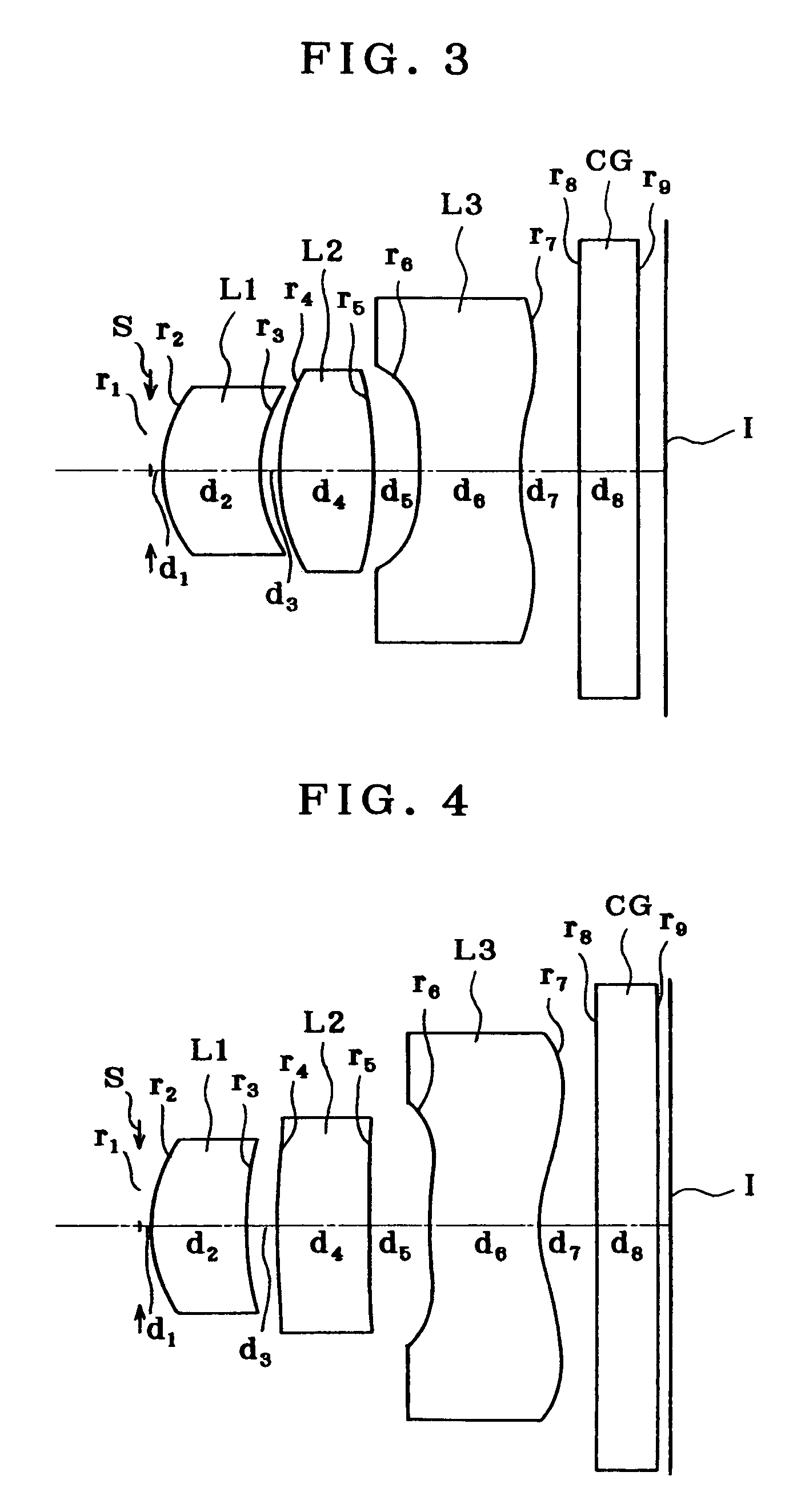
example 3
[0193]
r1 = ∞ (Stop)d1 = 0.10r2 = 1.295 (Aspheric)d2 = 0.81nd1 = 1.50913νd1 = 56.20r3 = 1.468d3 = 0.15r4 = 2.126d4 = 0.83nd2 = 1.50913νd2 = 56.20r5 = −6.380 (Aspheric)d5 = 0.38r6 =−10.735 (Aspheric)d6 = 0.90nd3 = 1.50913νd3 = 56.20r7 = 1.967 (Aspheric)d7 = 0.50r8 = ∞d8 = 0.50nd4 = 1.51633νd4 = 64.14r9 = ∞
Aspherical Coefficients[0194]2 nd surface[0195]K=0.000[0196]A4=−3.71837×10⁻² [0197]A6=7.63558×10⁻³ [0198]A8=0[0199]5 th surface[0200]K=−5.446[0201]A4=−1.27985×10⁻¹ [0202]A6=5.14883×10⁻² [0203]A8=0[0204]6 th surface[0205]K=0.000[0206]A4=−4.20900×10⁻¹ [0207]A6=3.44052×10⁻² [0208]A8=−5.77484×10⁻² [0209]7 th surface[0210]K=−13.683[0211]A4=−8.08690×10⁻² [0212]A6=1.71290×10⁻² [0213]A8=−1.33388×10⁻³
PUM
 Abstract
Description
Claims
Application Information
 - R&D
- Intellectual Property
- Life Sciences
- Materials
- Tech Scout
- Unparalleled Data Quality
- Higher Quality Content
- 60% Fewer Hallucinations
Browse by: Latest US Patents, China's latest patents, Technical Efficacy Thesaurus, Application Domain, Technology Topic, Popular Technical Reports.
© 2025 PatSnap. All rights reserved.Legal|Privacy policy|Modern Slavery Act Transparency Statement|Sitemap|About US| Contact US: help@patsnap.com