Optical crossbar using lasing semiconductor optical amplifiers

a technology of optical amplifier and optical crossbar, which is applied in the direction of optical elements, semiconductor lasers, instruments, etc., can solve the problems of limited physical expansion or building out a network, the inability of new software applications to function properly, and the inability to increase network utilization so much, so as to increase the speed through which data may be switched, reduce the number of electrical components, and enhance the conversion between electrical and optical signals

Inactive Publication Date: 2006-05-16
II VI DELAWARE INC
View PDF18 Cites 11 Cited by
  • Summary
  • Abstract
  • Description
  • Claims
  • Application Information

AI Technical Summary

Benefits of technology

[0009]The present invention overcomes the deficiencies and limitations of the prior art by providing an optical crossbar switch having a minimal number of electrical components, thereby increasing the speed through which data may be switched within the optical crossbar. In particular, the present invention utilizes various characteristics of a lasing semiconductor optical amplifier (SOA) within the optical crossbar switch to reduce the number of electrical components and enhance conversions between electrical and optical signals.

Problems solved by technology

In response, network software providers are spending large amounts of money in research and development to increase the quality and functionality of their software products that run on a network.
These new software applications require a large amount of network bandwidth to function properly.
However, network utilization can only increase performance so much before a ceiling is hit at which the network utilization is maximized.
Comparatively, physically increasing or building out a network usually is only limited to the actual physical expansion of the network (i.e. increase in fiber, switches, etc.) or the number of new channels placed within the network.
Generally, the time constraints of routing data within a network switch account for the majority of time required for data to travel across a network.
The time required to perform these electrical processes greatly reduces the rate at which data travels across a network, thereby decreasing the network bandwidth.
Decreasing the delay caused by electrical network components increases the speed at which the data will travel across the network resulting in an increase in bandwidth available on a network.

Method used


Image

  • Optical crossbar using lasing semiconductor optical amplifiers
  • Optical crossbar using lasing semiconductor optical amplifiers
  • Optical crossbar using lasing semiconductor optical amplifiers

Examples


Embodiment Construction

[0029]In the following description, for purposes of explanation, numerous specific details are set forth in order to provide a thorough understanding of the invention. It will be apparent, however, to one skilled in the art that the invention can be practiced without these specific details. In other instances, structures and devices are shown in block diagram form in order to avoid obscuring the invention.

[0030]Reference in the specification to “one embodiment” or “an embodiment” means that a particular feature, structure, or characteristic described in connection with the embodiment is included in at least one embodiment of the invention. The appearances of the phrase “in one embodiment” in various places in the specification are not necessarily all referring to the same embodiment.

[0031]A. Optical Crossbar Switch Overview

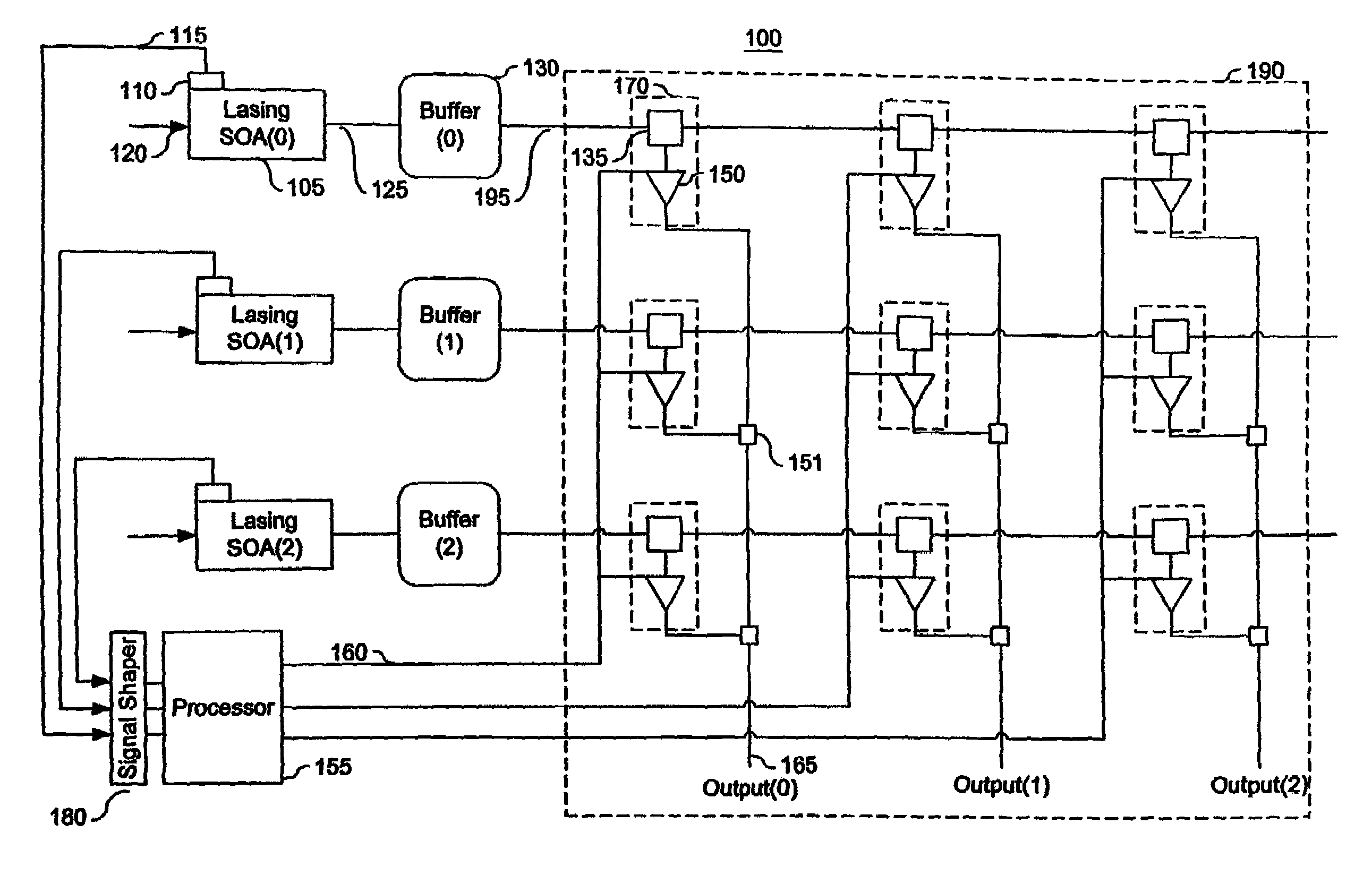
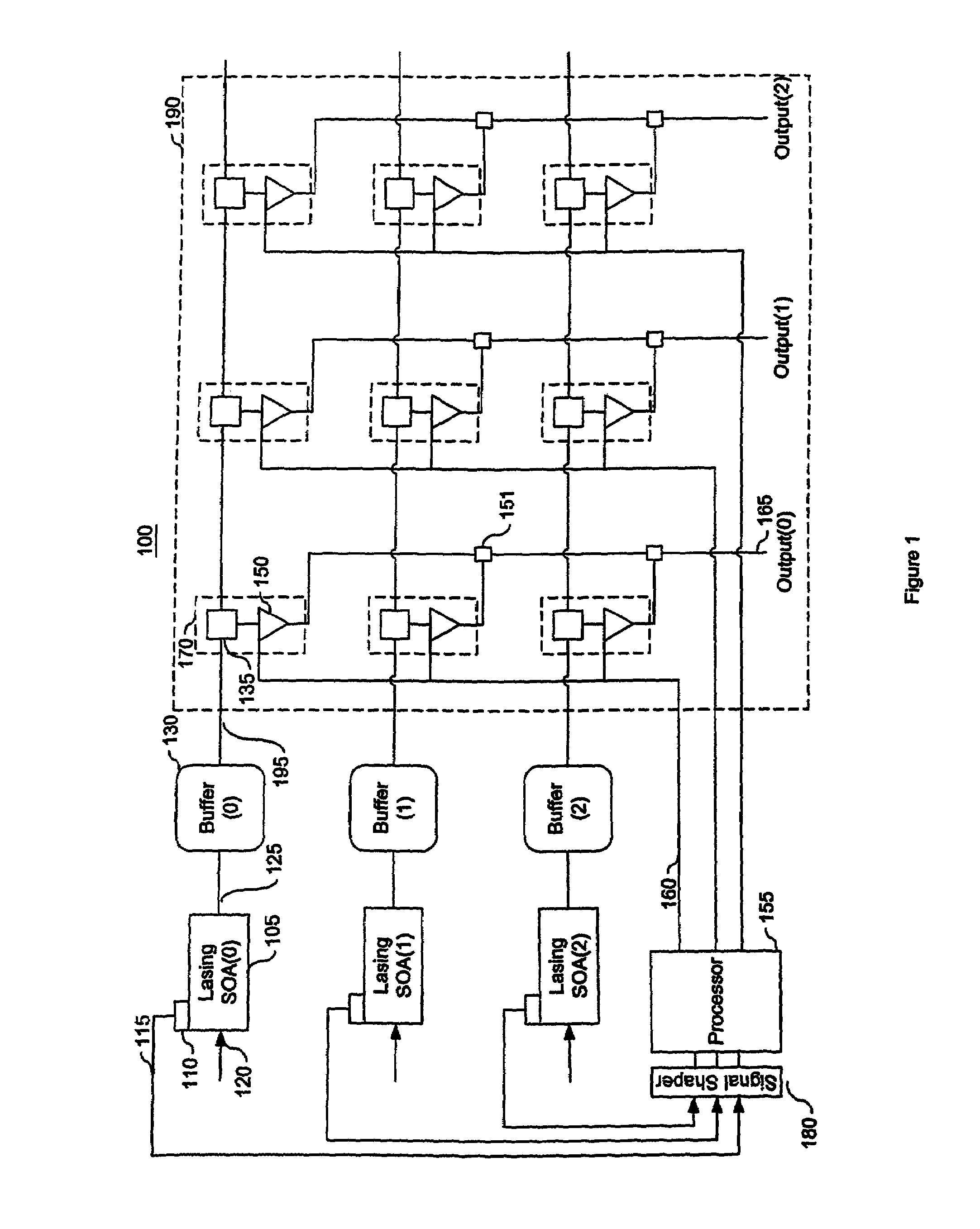
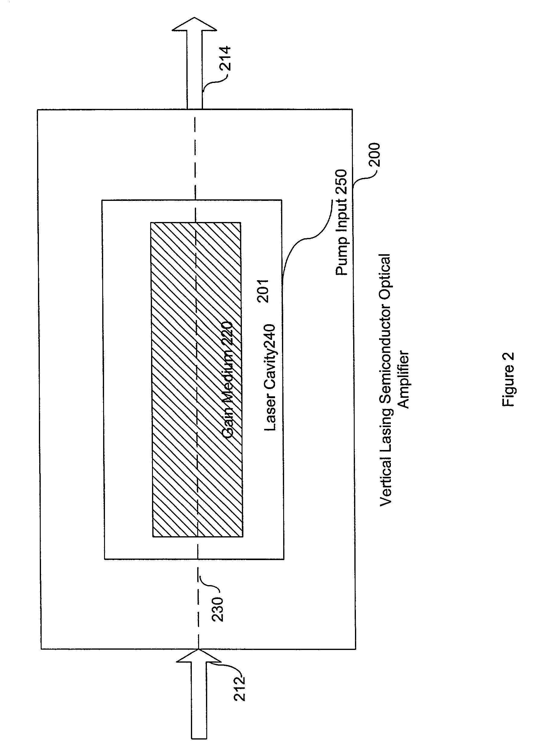
[0032]FIG. 1 is a block diagram of an optical crossbar switch 100 that reduces the number of electrical components. This switch 100 comprises lasing SOAs 105, mon...


PUM


Abstract

An optical crossbar switch is described that minimizes the number of electrical components and optimizes the conversion between optical and electrical signals. Utilizing various characteristics of lasing semiconductor optical amplifiers, the optical crossbar switch provides optical components in place of traditionally used electrical components. For example, an optical buffer is described that delays an optical signal a sufficient amount of time for a path to be created for the optical signal through the optical crossbar. Additionally, a monitor / detector circuit utilizes a ballast laser signal emitted from a lasing SOA during amplification of an optical signal in order to convert optical routing information to an electrical equivalent. As a result of the multiple uses of lasing semiconductor optical amplifiers, the bandwidth of the described optical crossbar switch is greater than traditional optical crossbar switches currently in use.

Description

CROSS-REFERENCE TO RELATED APPLICATIONS[0001]This application is a continuation-in-part of U.S. patent application Ser. No. 09 / 809,812, “Vertical Lasing Semiconductor Optical Amplifier (VLSOA) Packet Router,” by Sol. P Dijaili, Jeffrey D. Walker and Frank G. Patterson, filed Mar. 16, 2001; and claims priority from provisional U.S. Patent Application Ser. No. 60 / 255,753, “Optical Devices Including A Semiconductor Optical Amplifier,” by Jeffrey D. Walker, Sol P. DiJaili, John M. Wachsman, Frank G. Paterson, and James A Witham, filed Dec. 14, 2000, and provisional U.S. Patent Application Ser. No. 60 / 274,471, “Optical Crossbar Switch,” by Sol P. DiJaili and Jeffrey D. Walker, filed Mar. 9, 2001. The subject matter of all the foregoing is incorporated herein by reference.BACKGROUND[0002]A. Technical Field[0003]The present invention relates generally to an optical crossbar switch that may be used in an optical network and, more particularly, to an optical crossbar switch that implements v...

Claims


Application Information

Patent Timeline
IPC IPC(8): H01S3/00
CPCH04Q11/0005H01S5/1032H01S5/18308H01S5/2027H01S5/423H01S5/5072H04Q2011/0083H04Q2011/0013H04Q2011/0016H04Q2011/002H04Q2011/0039H04Q2011/0058
Inventor DIJAILI, SOL P.WALKER, JEFFREY D.
Owner II VI DELAWARE INC
Why Eureka
Try Eureka