Eureka AIR delivers breakthrough ideas for toughest innovation challenges, trusted by R&D personnel around the world.

Simple scenario builder

a scenario builder and scenario technology, applied in the field of software diagnostics, can solve problems such as lack of reporting, developers may be unable to accurately diagnose problems, and problems encountered when using applications, and achieve the effect of diagnosing application faults at a high level

Inactive Publication Date: 2006-05-09
IBM CORP
View PDF15 Cites 19 Cited by
  • Summary
  • Abstract
  • Description
  • Claims
  • Application Information

AI Technical Summary

Benefits of technology

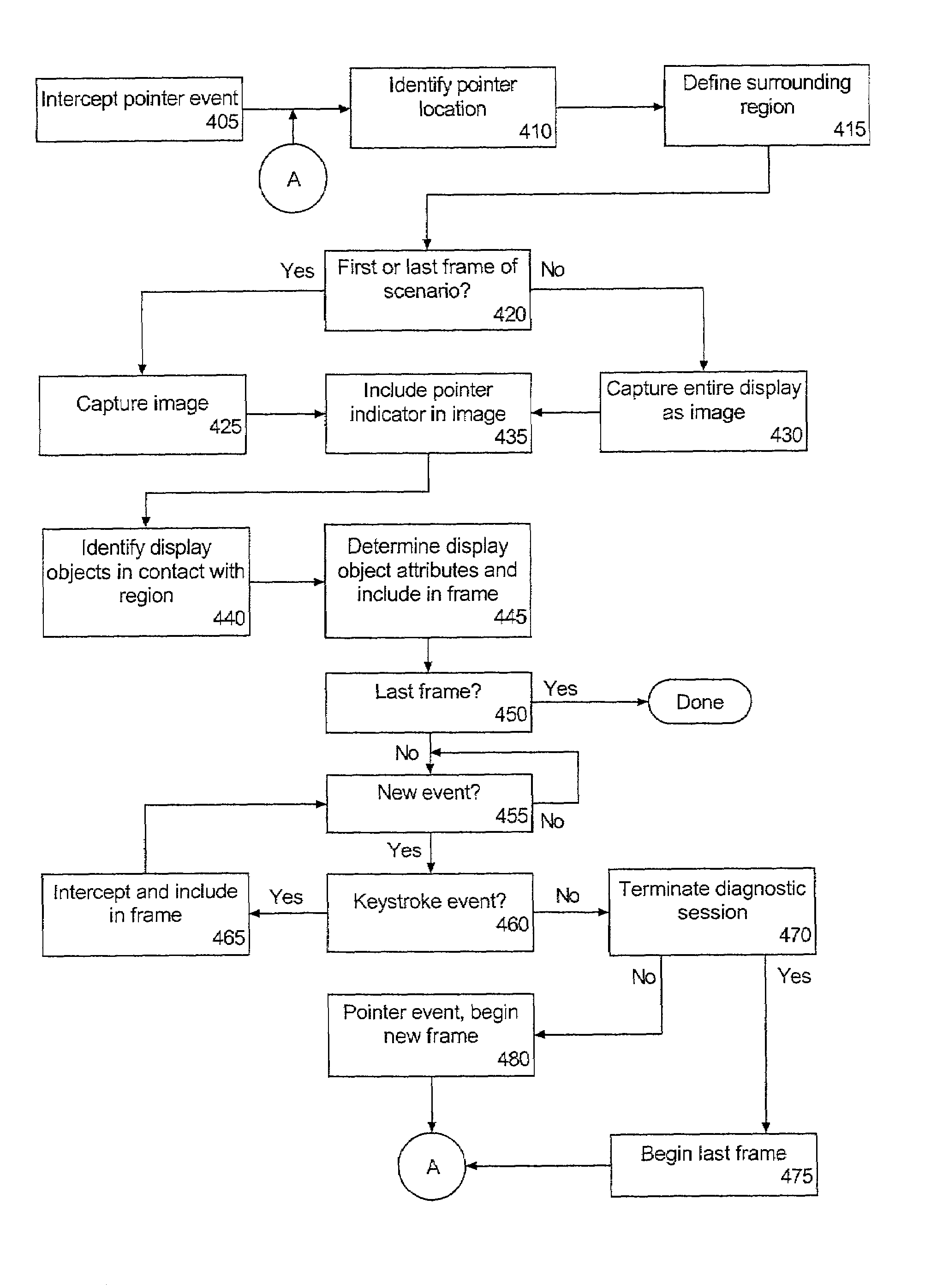
The present invention provides a solution for diagnosing application problems such as performance related issues, application faults, failures, and other problematic behavior. It involves recording user interactions with an application and its various graphical user interfaces, as well as recording other application information to produce a record of events and application information prior to a fault. The resulting diagnostic information can provide a comprehensive view of the inner-workings and external events leading up to a particular application fault. The invention also includes a method of constructing a diagnostic scenario by intercepting user input events, capturing an image of a region surrounding the user input event, and generating a diagnostic frame specifying the image, and text representing attributes of the intercepted user input event. The invention also includes an application diagnostic tool that can intercept user initiated events and generate an image of a display, with associated textual information. The data repository can store the image and the textual information, which can be associated with the image.

Problems solved by technology

Problems encountered when using an application go unreported in many cases.
This lack of reporting occurs largely due to the burden placed on the user to collect adequate information for diagnosing an application fault or failure.
In cases where application faults are reported, however, developers may be unable to accurately diagnose the problem due to the scarcity of information which is actually collected by the user.
For example, although the user may collect information provided in an application fault message, frequently this information is limited to information specific to the internal workings of the application, such as the location in memory where the fault occurred and the values of particular processor registers.
Moreover, such information fails to provide any insight as to the series of application-user interactions leading up to the application fault.
Because most tracing utilities operate on a micro-level, or in other words, the utilities focus only on the inner workings of an application, these conventional tracing utilities also are unable to portray higher level interactions between a user and the application.

Method used


Image

  • Simple scenario builder
  • Simple scenario builder
  • Simple scenario builder

Examples


Embodiment Construction

[0016]The invention disclosed herein provides a solution for diagnosing application problems such as performance related issues, application failures, faults, errors, and other problematic application behavior (hereafter collectively referred to as faults). In particular, the present invention can collect information relating to both user interactions with an application as well as other information relating to the application itself. The resulting diagnostic information can be provided as a series of sequential frames including both images and textual information. When viewed, the frames can represent a scenario portraying both user actions and the inner-workings of an application in the time leading up to an application fault.

[0017]FIG. 1 is a schematic diagram illustrating a diagnostic utility 100 in accordance with the inventive arrangements disclosed herein. The diagnostic utility 100 can intercept various events, for example any user interaction with a monitored application, r...


PUM


Abstract

A method of constructing a diagnostic scenario can include intercepting at least one user input event, capturing an image of a region surrounding the user input event, and generating a diagnostic frame specifying the image and text representing attributes of the intercepted user input event.

Description

BACKGROUND OF THE INVENTION[0001]1. Technical Field[0002]The invention relates to the field of software diagnostics, and more particularly, to recording application related and user interaction information for diagnosing application problems.[0003]2. Description of the Related Art[0004]Problems encountered when using an application go unreported in many cases. This lack of reporting occurs largely due to the burden placed on the user to collect adequate information for diagnosing an application fault or failure. As is often the case, the user is presented with a message indicating that an application fault has occurred. It then becomes incumbent upon the user to make note of the pertinent information in the fault message so that the data is not lost.[0005]In cases where application faults are reported, however, developers may be unable to accurately diagnose the problem due to the scarcity of information which is actually collected by the user. For example, although the user may col...

Claims


Application Information

Patent Timeline
Patent Type & Authority Patents(United States)
IPC IPC(8): G06F11/00G06F11/36
CPCG06F11/3636G06F11/3684G06F11/3664G06F11/366
Inventor BROWN, JERRY RICHARD
Owner IBM CORP
Why Eureka
Eureka Blog
Learn More