
Dual radius twist lock radome and reflector antenna for radome

a technology of twist lock and radome, which is applied in the field of radomes, can solve the problems of generating a return loss, generating a discontinuity of rf signal path, and burdening the associated plurality of springs, clips, screws, or brackets,

Inactive Publication Date: 2006-05-09
COMMSCOPE TECH LLC
View PDF24 Cites 22 Cited by
  • Summary
  • Abstract
  • Description
  • Claims
  • Application Information

AI Technical Summary

Benefits of technology

The design improves RF signal pattern, reduces return loss, and simplifies installation by minimizing mechanical fasteners, enhancing structural integrity and reducing wind load and snow / ice buildup.

Problems solved by technology

The associated plurality of springs, clips, screws, and or brackets are a significant burden during installation and or service of the reflector antenna high upon radio towers or other difficult to access locations.
The radome also creates an impedance discontinuity within the RF signal path that generates a return loss due to RF reflections off of the radome directly or via further reflections back into the antenna feed.
However, the significantly reduced focal length of the inner parabioloidal portion necessary to direct the RF energy to the back of the sub reflector causes the radome to have a significant center protrusion and associated additional structural mass, negatively affecting the windload and or other structural requirements of the radome, reflector antenna and support structure.

Method used


Image

  • Dual radius twist lock radome and reflector antenna for radome
  • Dual radius twist lock radome and reflector antenna for radome
  • Dual radius twist lock radome and reflector antenna for radome

Examples


Embodiment Construction

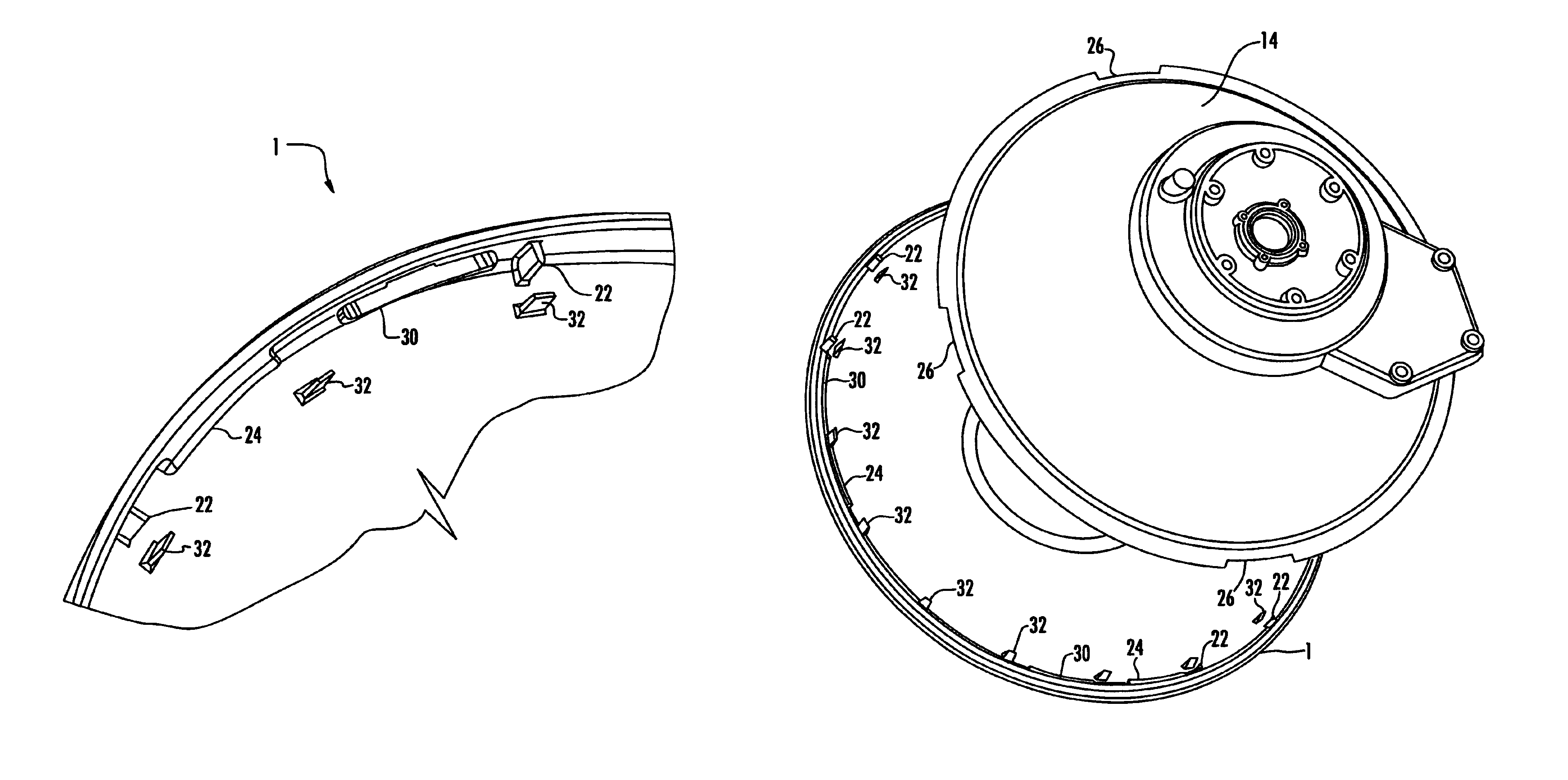
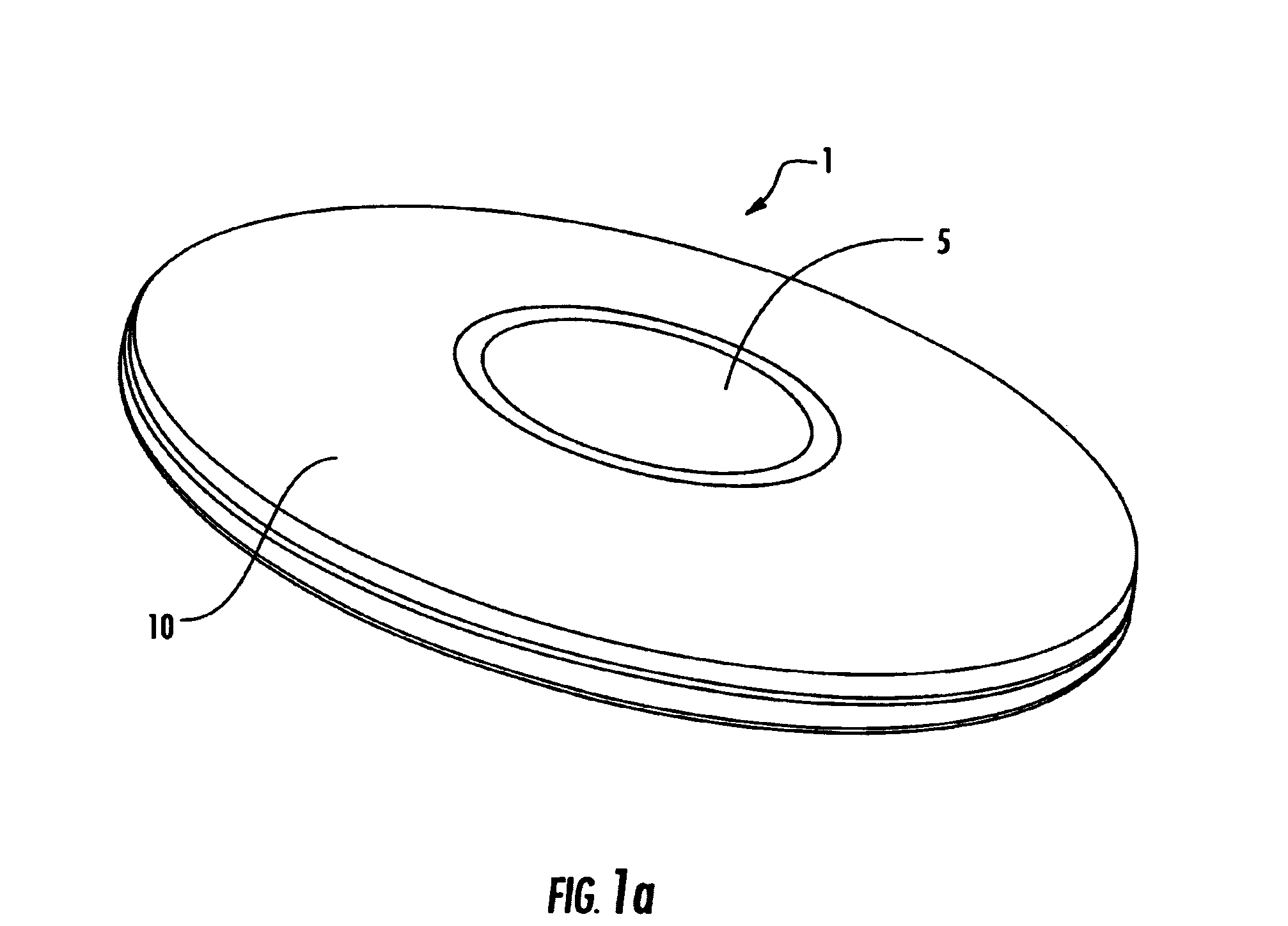
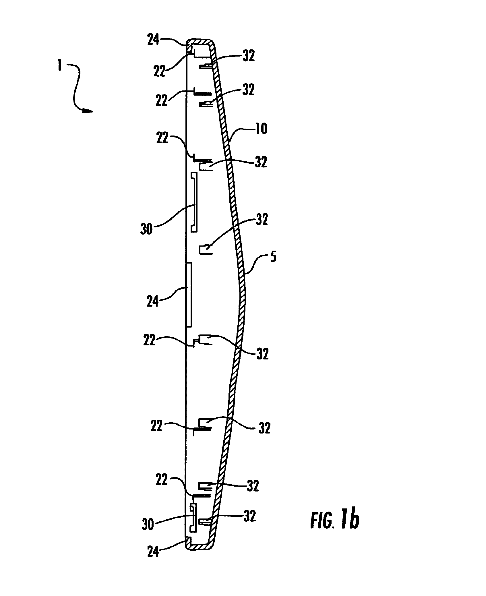
[0020]Signals reflected from a radome surface that is tangential to the desired signal direction would be straight back into the signal path, contributing to the return loss of the reflector antenna. Also, reflections proximate the feed assembly encounter multiple surfaces from which to launch reflections that may finally be directed back to the feed, further contributing to return loss. A radome with a small radius reflects signals out of the signal path but also degrades the far field radiation pattern. Further, radomes with small radius configurations have an extended dimension along the signal axis of the reflector antenna, increasing the wind load and associated mechanical strength requirements for the reflector antenna and antenna support structure. The present invention utilizes a very large radius in an outer portion and a smaller radius for a central portion that is significantly larger (has a focal point at the reflector vertex area rather than the back side of the antenna...


PUM


Abstract

A radome and a reflector antenna configured to mate with the radome. The radome has a central portion and a surrounding outer portion. The central portion having a radius selected to redirect a reflected component of the transmitted RF signal from the radome to the vertex area of the reflector. The outer portion has a larger radius selected to minimize radiation pattern degradation. RF absorbing material located at the vertex area reduces return loss of the reflector antenna. The radome attaches to the reflector via a plurality of tabs formed proximate the periphery of the radome that correspond to a plurality of cut outs in the periphery of the reflector. When inserted and rotated, the radome secures to the reflector without requiring tools.

Description

BACKGROUND OF INVENTION[0001]1. Field of the Invention[0002]This invention relates to radomes and more particularly to a radome and reflector antenna pair having ease of installation and improved reflection / transmission characteristics.[0003]2. Description of Related Art[0004]Reflector antennas are used in, for example, communications systems. Radomes are used to cover the open end of the reflector to minimize wind loading and antenna performance degradation due to environmental fouling of the antenna reflector and or feed assembly.[0005]Reflector antennas are subject to expansion and contraction due to temperature change. The reflector and the radome are formed from different materials, typically having different expansion coefficients. The interconnection between the radome and the reflector should accommodate differential expansion between the radome material and the reflector material, without compromising the mechanical attachment integrity or environmental seal between the rad...

Claims


Application Information

Patent Timeline
Patent Type & Authority Patents(United States)
IPC IPC(8): H01Q19/00H01Q1/42H01Q19/02
CPCH01Q19/022H01Q1/42
Inventor SYED, JUNAIDLEWRY, MATTHEWTHOMSON, GRAEMELAWSON, BRIAN
Owner COMMSCOPE TECH LLC
Learn More