Collet load shoulder

a load shoulder and collapsible technology, applied in the direction of sealing/packing, mechanical equipment, borehole/well accessories, etc., can solve the problem of extra trip into the wellhead housing

Active Publication Date: 2006-05-09
VETCO GRAY
View PDF10 Cites 33 Cited by
  • Summary
  • Abstract
  • Description
  • Claims
  • Application Information

AI Technical Summary

Problems solved by technology

Both of these methods require an extra trip into the wellhead housing, which is costly in deep water.

Method used


Image

  • Collet load shoulder
  • Collet load shoulder
  • Collet load shoulder

Examples


Embodiment Construction

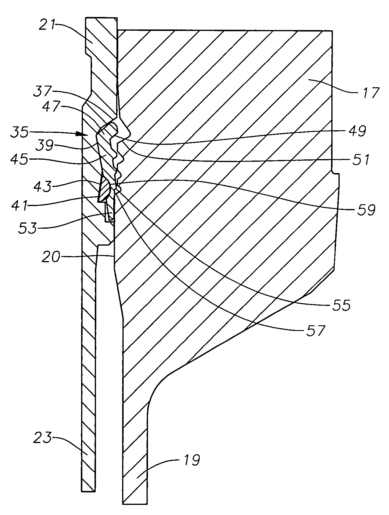
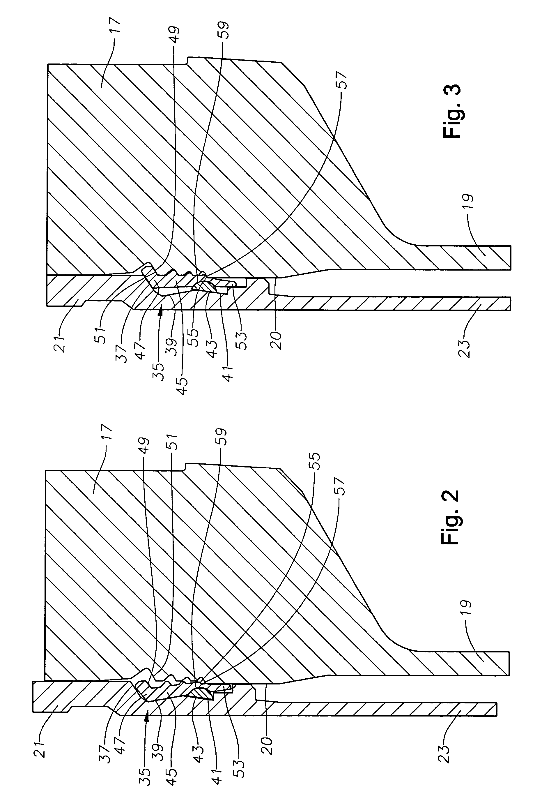
[0018]Referring to FIG. 1, a subsea wellhead assembly 11 includes a low pressure or outer wellhead housing 13 with a string of conductor casing 15 extending from its lower end to a desired depth within the well. A high pressure or inner wellhead housing 17 with a string of casing 19 extending from its lower end lands within low pressure wellhead housing 13. Casing 19 extends to a deeper depth within the well. High pressure wellhead housing 17 has a bore 20 extending axially therethrough. In the preferred embodiment, bore 20 has a predetermined diameter defining a “full bore” diameter for wellhead assembly 11. That is, there are no significant reductions in inner diameter throughout bore 20. In the example shown, casing 19 has a slightly larger bore diameter than high pressure wellhead housing 17.

[0019]Casing hanger 21 with a first intermediate string of casing 23 extending below is lowered into and lands in bore 20 of high pressure wellhead housing 17. After cementing, a pack-off or...


PUM


Abstract

In a subsea wellhead assembly, a collet ring assembly is used with a hanger for suspending a string of conduit in a subsea wellhead assembly. The ring assembly includes a collet that extends around an outer surface of the hanger. The collet has an upper portion that rotates radially between locked and unlocked positions. The ring assembly has a protruding lower portion extending radially outward from the hanger for engaging an interior surface of the wellhead assembly, which causes the upper portion of the collet to rotate radially outward to engage the interior surface of the wellhead assembly in a locked position. The ring assembly includes a back-up ring that engages the interior of the collet, which the collet rotates around between its locked and unlocked positions.

Description

BACKGROUND OF THE INVENTION[0001]1. Field of the Invention[0002]The present invention relates generally to devices for connecting a tubular member with a tubular housing, and in particular to a locking ring that connects a casing hanger to a wellhead housing.[0003]2. Background of the Invention[0004]Generally a subsea high pressure wellhead housing has a landing shoulder within it for supporting a string of casing. The landing shoulder results in the portion of the bore below it being smaller in diameter than the bore portion above it. The reduced diameter of the lower portion of the bore limits the size of casing that can be ran through and supported in the wellhead housing. If a second casing string is required for a deeper portion of the well, it would have to pass through the first string. The diameter of the second string limits the size of tubing, pumps and the like that will be run through it. To avoid very large diameter wellhead housings, operators desire to minimize the di...

Claims


Application Information

Patent Timeline
Patent Type & Authority Patents(United States)
IPC IPC(8): E21B7/12E21B33/043
CPCE21B33/043
Inventor JENNINGS, CHARLES E.SHIRANI, ALIREZA
Owner VETCO GRAY
Why Eureka
Try Eureka