Pressure regulator including a fixed valve ball and method of assembling the same

a technology of pressure regulator and fixed valve ball, which is applied in the direction of fluid pressure control, process and machine control, instruments, etc., can solve the problem of misalignment between the valve ball and the valve sea

Inactive Publication Date: 2006-05-09
SIEMENS VDO AUTOMOTIVE CORP
View PDF16 Cites 4 Cited by
  • Summary
  • Abstract
  • Description
  • Claims
  • Application Information

AI Technical Summary

Benefits of technology

[0005]The present invention provides a pressure regulator that includes a housing, a divider, and a valve. The housing includes an inlet and an outlet. The divider separates the housing into a first chamber and a second chamber. And the valve includes a spherical valve ball and a seat. The spherical valve ball is fixed with respect to a first one of the housing and the divider, and the seat is fixed with respect to a second one of the housing and the divider. A first configuration of the spherical valve ball with respect to the seat substantially prevents fluid communication between the inlet and the outlet, and a second configuration of the spherical valve ball with respect to the seat permits fluid communication between the inlet and the outlet.

Problems solved by technology

It is believed that tolerances in pressure regulator components, and tolerances in pressure regulator assembly equipment, along with the inherent unbalanced forces applied by a compression spring to a diaphragm assembly, can cause misalignment between a valve ball and a valve seat.
The known fuel pressure regulator suffers from a number of disadvantages, including a valve ball assembly that includes a plurality of parts that must be sub-assembled before the valve ball assembly can be installed in the known fuel pressure regulator.

Method used


Image

  • Pressure regulator including a fixed valve ball and method of assembling the same
  • Pressure regulator including a fixed valve ball and method of assembling the same
  • Pressure regulator including a fixed valve ball and method of assembling the same

Examples


Embodiment Construction

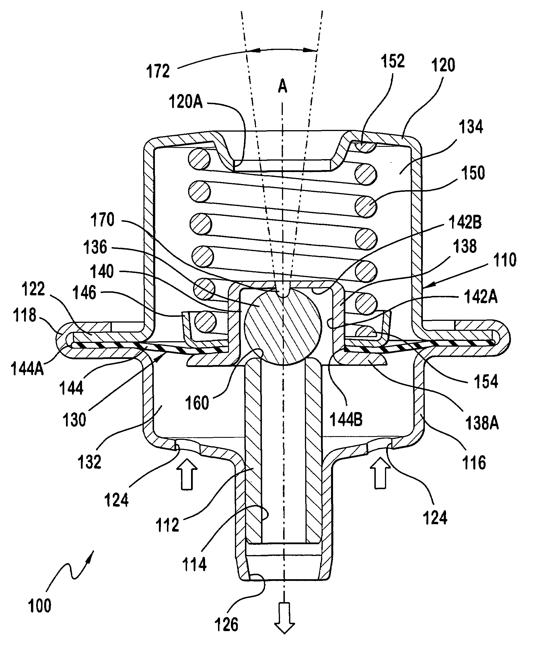
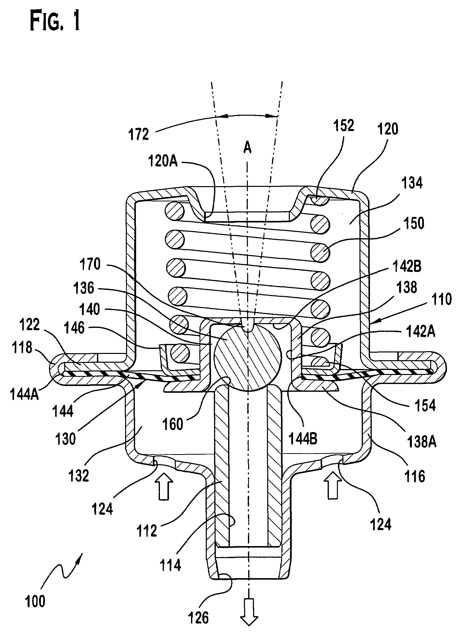
[0010]FIG. 1 illustrates a by-pass valve type of pressure regulator 100 according to the present invention. The pressure regulator 100 includes a housing 110. The housing 110 is separated by a divider 130 into a first chamber 132 and a second chamber 134. The divider 130 includes a spherical valve ball 136 that cooperates with a seat 112, which is fixed to the housing 110, and defines a passage 114. In a first configuration, the spherical valve ball 136 sealingly engages the seat 112 so as to prevent fluid communication between the first chamber 132 and the passage 114. And in a second configuration, the spherical valve ball 136 is spaced from the seat 112 so as to permit fluid communication between the first chamber 132 and the passage 114.

[0011]The housing 110 includes a first housing part 116 with a first flange 118, and includes a second housing part 120 with a second flange 122. The first housing part 118 also includes at least one fluid inlet 124 (two are shown) and a fluid ou...


PUM


Abstract

A pressure regulator includes a housing, a divider, and a valve. The housing includes an inlet and an outlet. The divider separates the housing into a first chamber and a second chamber. And the valve includes a spherical valve ball and a seat. The spherical valve ball is fixed with respect to a first one of the housing and the divider, and the seat is fixed with respect to a second one of the housing and the divider. A first configuration of the spherical valve ball with respect to the seat substantially prevents fluid communication between the inlet and the outlet, and a second configuration of the spherical valve ball with respect to the seat permits fluid communication between the inlet and the outlet.

Description

FIELD OF THE INVENTION[0001]This invention relates to a pressure regulator for automotive fuel systems, and more particularly to by-pass valve or flow-through type pressure regulators having a fixed spherical valve ball.BACKGROUND OF THE INVENTION[0002]Most modern automotive fuel systems utilize fuel injectors to deliver fuel to the engine cylinders for combustion. The fuel injectors are mounted on a fuel rail to which fuel is supplied by a pump. The pressure at which the fuel is supplied to the fuel rail must be metered to ensure the proper operation of the fuel injectors. Metering is carried out using pressure regulators that control the pressure of the fuel in the system at all engine r.p.m. levels.[0003]It is believed that tolerances in pressure regulator components, and tolerances in pressure regulator assembly equipment, along with the inherent unbalanced forces applied by a compression spring to a diaphragm assembly, can cause misalignment between a valve ball and a valve sea...

Claims


Application Information

Patent Timeline
Patent Type & Authority Patents(United States)
IPC IPC(8): G05D16/08F16K31/365G05D16/02F02M69/54F16K17/04F16K17/08F16K31/126G05D16/06
CPCF02M69/54F16K17/0406G05D16/0655F16K31/1262F16K17/085G05D16/024Y10T137/7836
Inventor WYNN, JR., JAMES ARCHIE
Owner SIEMENS VDO AUTOMOTIVE CORP
Why Eureka
Try Eureka