
Device and method for the dynamic allocation of frequencies for multicarrier modulation systems

a multi-carrier modulation and frequency allocation technology, applied in the field of information transmission, can solve problems such as erroneous detection, distortion of symbols, and interference between symbols

Inactive Publication Date: 2006-05-02
CANON KK
View PDF10 Cites 66 Cited by
  • Summary
  • Abstract
  • Description
  • Claims
  • Application Information

AI Technical Summary

Benefits of technology

[0049]The present invention relates to an improved method of efficiently transmitting information using multi-carrier modulation.

Problems solved by technology

Any distortions will give rise to interference between symbols, which must be negated with an equalizer.
As a result of flaws in the transmission channel, a transmitted symbol can contain errors on reception, and, if the errors are detected, retransmission may be required.
If the procedure were not applied, a single symbol would be affected by a large evaluation error, leading to erroneous detection.
This conventional mode of transmission using OFDM does, however, have a major drawback.
Such critical sequences may cause difficulties for the downstream devices as, in practice, amplifiers and modulators may lack the fidelity to process swift amplitude variations.
As a result clipping, which is the non-transmission of the signal peaks, may occur, resulting in the loss of corresponding information.
Furthermore, harmonic distortion, one of the major problems of transmission systems, may be introduced, and may be impossible to negate.
This process induces a slight deterioration in the bit error rate.
All these currently implemented solutions have the drawback either of adversely affecting the bit rate of the transmission, impairing the quality of the transmission, or of being complicated.

Method used


Image

  • Device and method for the dynamic allocation of frequencies for multicarrier modulation systems
  • Device and method for the dynamic allocation of frequencies for multicarrier modulation systems
  • Device and method for the dynamic allocation of frequencies for multicarrier modulation systems

Examples


first embodiment

[0327]The block diagram of FIG. 15 depicts a more detailed view of a peripheral station, for example of the station 1402, which comprises a data source 2020 and a communication device 2022.

[0328]In general terms, the communication device 2022 is a device for sending and receiving information according to the present invention.

[0329]This information is intended to be transmitted over a radio communication channel, in the form of carriers modulated by said information.

[0330]The data source 2020 is for example a digital camera, a computer, a printer, a server, a facsimile machine, a scanner, a digital camera, a digital photographic apparatus, a television, a video recorder or a decoder.

[0331]This communication device 2022 includes a data processing unit 2024 comprising a calculating unit 2026, a RAM 2028, a ROM 2030, a bus interface 2032 and a bus 2034 which connects the data source 2020 to said interface.

[0332]The communication device 2022 comprises a bus 2036 serving the calculating ...

second embodiment

[0463]The peripheral communication station 2802 depicted in FIG. 28 concerns the invention.

[0464]In FIG. 28, all the elements are unchanged compared with those of FIG. 15 and have the same references.

[0465]The peripheral station 2802 has a data source 2020 and an communication device 2200.

[0466]This communication device 2200 has a data processing unit 2202 which comprises a calculating unit 2026, a bus interface 2032 and a bus 2034 which connects the data source 2020 to the bus interface 2032. The data processing unit 2202 also comprises a modem interface 2038, a RAM 2204 and a ROM 2206.

[0467]The computing device 2200 also includes an information sending unit 2208 connected to a radio module 2044, which is equipped with an antenna 2046.

[0468]The communication device 2200 also includes an information reception unit 2210 connected to the radio module 2044 and a modem interface 2038.

[0469]As depicted in FIG. 28, the bus interface 2032, the calculating unit 2026, the modem interface 203...


PUM


Abstract

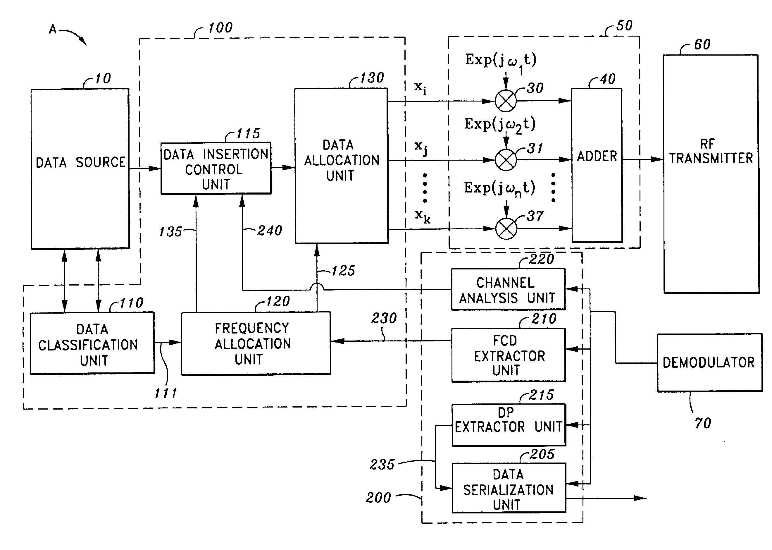
The method of transmitting data in the form of symbols sent over an electromagnetic channel is characterized in that a measurement of significance is attributed to each group of data to be transmitted, in that the transmission reliability of the carriers is estimated dynamically, and in that the most significant data are sent over the most reliable carriers at each instant, the other data being sent over the carriers of decreasing reliability, in decreasing order of significance of the data.

Description

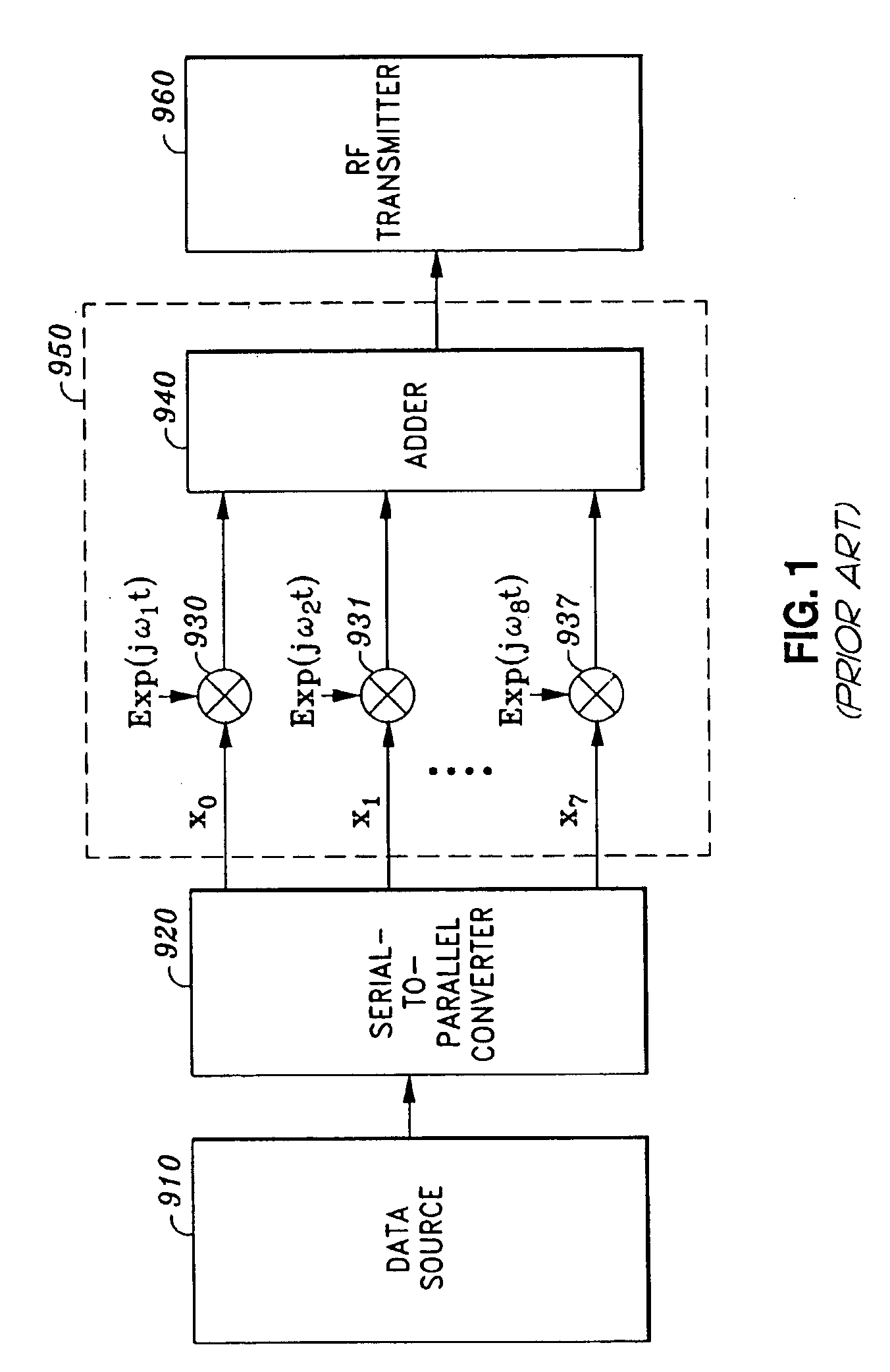
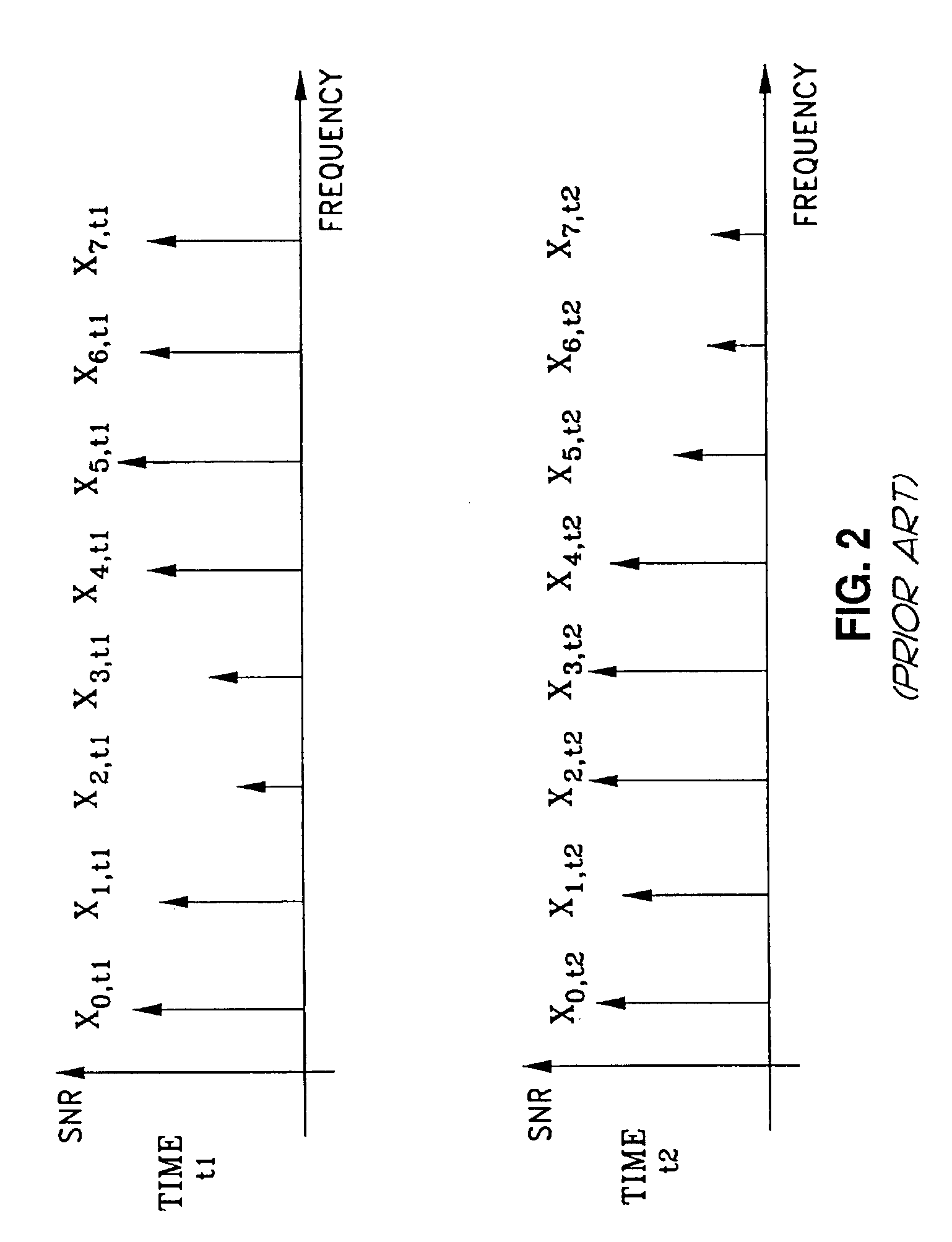
BACKGROUND OF THE INVENTION[0001]1. Field of the Invention[0002]The invention relates to the transmission of information in the form of an electromagnetic signal. In particular, the invention concerns the allocation of carrier frequencies for transmission systems using multi-carrier type modulation and the process for reducing the ratio of peak amplitude to mean amplitude usually required in transmission systems using multi-carrier type modulation.[0003]2. Description of the Related Art[0004]An information transmission system generally sends symbols serially, where each symbol can be a sequence of binary data. Consequentially, the frequency band required to send the symbols must be larger than the inverse of the length of a symbol. When the symbol transmission rate becomes to high, the channel must have identical amplitude and phase characteristics over the entire space of the frequencies which constitute the passband. Any distortions will give rise to interference between symbols, ...

Claims


Application Information

Patent Timeline
IPC IPC(8): H04L27/10
CPCH04L5/0007H04L5/006H04L5/0064H04L5/0085H04L5/0042H04L5/0044H04L5/0096H04L5/0053
Inventor THOUMY, FRANCOISLE BARS, PHILIPPEROUSSELIN, SAMUELLE SCOLAN, LIONELEHRMANN, FREDERIQUE
Owner CANON KK
Learn More