
Warped plane phased array monopulse radar antenna

a phased array and radar antenna technology, applied in the direction of antennas, instruments, antenna adaptation in movable bodies, etc., can solve the problems of difficult to obtain a useable azimuth difference signal, and difficulty in effective derive of azimuthal monopulses

Inactive Publication Date: 2006-05-02
NORTHROP GRUMMAN SYST CORP +1
View PDF5 Cites 40 Cited by
  • Summary
  • Abstract
  • Description
  • Claims
  • Application Information

AI Technical Summary

Benefits of technology

[0012]It is additionally an object of the invention to eliminate the need for two sets of phase shifters as employed in the current technology.

Problems solved by technology

This physical rotation makes it difficult to effectively derive an azimuthal monopulse.
However, it is difficult to obtain a useable azimuth difference signal while maintaining effective frequency scan in azimuth associated with the end row feed rows, while concurrently maintaining low sidelobe characteristics.

Method used


Image

  • Warped plane phased array monopulse radar antenna
  • Warped plane phased array monopulse radar antenna
  • Warped plane phased array monopulse radar antenna

Examples


Embodiment Construction

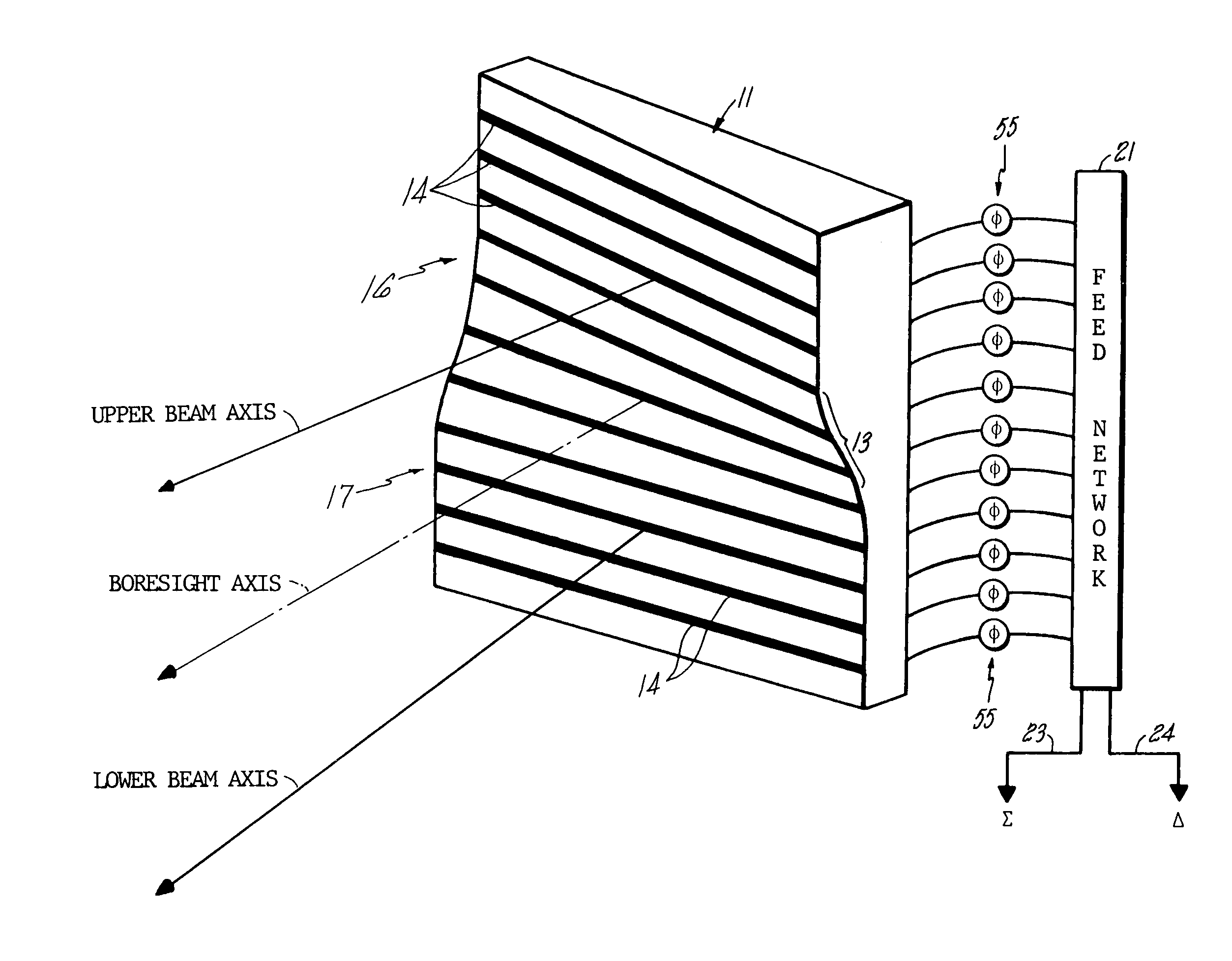
[0028]FIG. 1 schematically shows a phased array phase-amplitude monopulse radar antenna subject to gradual warp 13, effective for reorienting the azimuthal disposition of radiating rows 14 in the radar array in an incremental fashion. An upper section of radiating rows 16 is rightwardly skewed and a lower section of radiating rows 17 is leftwardly skewed with respect to the boresight axis. The array is thus separated into segregated upper and lower sections for radiating separate skewed beams A and B of electromagnetic energy toward a target region. The beams are initially vertically spaced but spread into a horizontally spaced relationship in the target region, permitting the establishment of phase-amplitude monopulse signals which can be resolved into useful target information.

[0029]The return signal from a detected target is received by the upper and lower sections of the antenna array, effectively returning through the same feed network 21, thereby producing sum and difference m...


PUM


Abstract

A phased array, phase-amplitude monopulse antenna arrangement for ground, shipboard or airborne radar systems. The phased array antenna is systematically warped and projects partially overlapping, separate beams from upper and lower regions of the array. A single set of phase-shifters is employed with a simplified feed structure to permit development of both azimuthal and elevation angle error signals in signal processing circuitry for target analysis.

Description

[0001]This is a continuation of application Ser. No. 06 / 576,849, filed Feb. 3, 1994, now abandoned.TECHNICAL FIELD[0002]This invention relates to a phased array phase-amplitude monopulse radar antenna arrangement, and more particularly to a phased array phase-amplitude monopulse antenna for ground, airborne or ship-based radar systems which combine electronic beam steering in one axis, e.g. elevation, and monopulse angle error measurement in both elevation and azimuthal axes while using a single set of row phase shifters.BACKGROUND ART[0003]The use of a phase-amplitude array antenna is particularly suited for use in radar systems which are mechanically scanned about one axis and electrically scanned about a second axis. Because of its high degree of versatility, such a radar can simultaneously provide angular elevation and azimuth target position measurements.[0004]The array antenna includes a plurality of vertically and horizontally arranged radiating elements suitably spaced from ...

Claims


Application Information

Patent Timeline
Patent Type & Authority Patents(United States)
IPC IPC(8): H01Q3/22G01S13/00H01Q3/26
CPCH01Q1/28H01Q25/02H01Q3/26H01Q3/30H01Q1/34G01S13/4463
Inventor CHUBB, JR., CHARLES F.SUTKIN, SEYMOUR
Owner NORTHROP GRUMMAN SYST CORP
Learn More