
Device for parallel metering of liquids

a technology for liquid meters and devices, applied in the direction of instruments, printing, burettes/pipettes, etc., can solve the problems of inability to accurately measure liquids, especially by means of disclosed devices, and achieve the effect of increasing the number of liquids which can be measured on a small spa

Active Publication Date: 2006-05-02
BOEHRINGER INGELHEIM MICROPARTS
View PDF5 Cites 27 Cited by
  • Summary
  • Abstract
  • Description
  • Claims
  • Application Information

AI Technical Summary

Benefits of technology

[0011]In such a device, the transfer means and thus the secondary channel arrangements are assigned at least one means for preventing the fluidic connection of the secondary channels to the chamber. This means for preventing a fluidic connection thus prevents venting of the device via the means for transferring the pressure surges after the assigned secondary channel has been emptied via the respective outlet. This ensures that the secondary channel arrangements can also be emptied in succession in time and the metered liquids contained in them can be expelled. The pressure surge that causes emptying can be produced by a single means for producing a pressure surge which expels the metered liquid from the device.
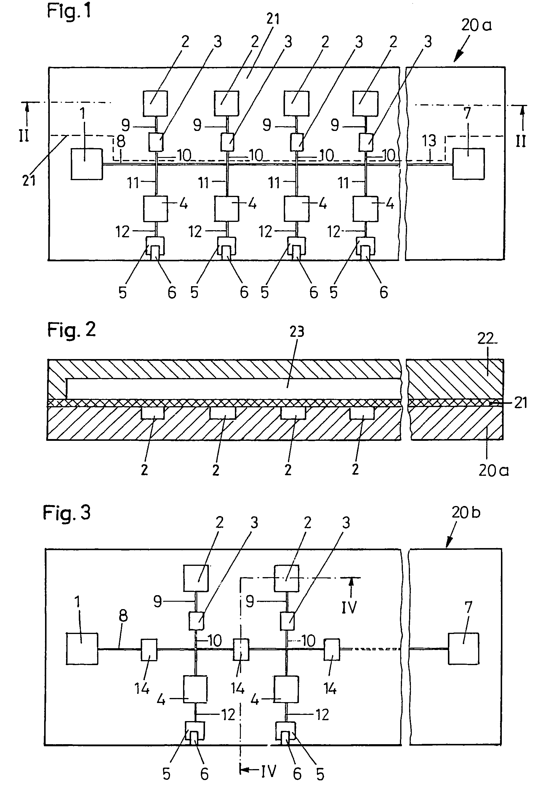
[0020]The first film can lie on the first outside surface of the first body. The first film can be attached to the first body by bonding. The first film can cover at least the first recesses and thus can prevent a fluidic connection out of the secondary channels via the first recesses to the remaining device. The first film as claimed in the invention can be attached to the body in the area of the first recess by bonding so that the film in the areas that adjoin the edge of the recess is securely connected to the first body.
[0023]Because the first recesses in the area of the entries of the secondary channels into the first recesses are vertical, the first film is prevented from arching into the first recess when a pressure is applied such that the entries of the secondary channels into the first recess are closed. The pressure surges can therefore be transferred into the secondary channels.
[0032]The third recesses can have lateral boundary surfaces which fall away flatly from at least one part of the edges to the bottom. The recess can thus simulate the shape of the films arching into the third recess under the action of a pressure surge. Thus it is possible for the film to distinctly increase the flow resistance of the valve or to make a connection via the valves impossible. The flatly sloping lateral boundary surfaces can be tilted at an angle between 5 to 45 degrees.
[0037]The volumes of the metering means and / or of the secondary channels and / or of the main channel can fix the volume of the amount of liquid which can be metered, by which a liquid excess can be minimized. The outlets for the liquid can be matched to a suitable grid size (for example 4.5 or 2.25 mm) so that the liquids can be dispensed precisely for example into a microliter plate.
[0044]The first body can be made from plastics (for example by molding, stamping, cutting or casting), metal, wax, rubber, silicon, glass, ceramic or the like. It is likewise conceivable for the system consisting of channels and recesses to be located on the two sides of the first body. In this way the number of amounts of liquid which can be metered on a small space can be increased.

Problems solved by technology

In the embodiment disclosed in this document, metering, especially accurate metering by means of the disclosed device, is not possible.

Method used


Image

  • Device for parallel metering of liquids
  • Device for parallel metering of liquids
  • Device for parallel metering of liquids

Examples


Embodiment Construction

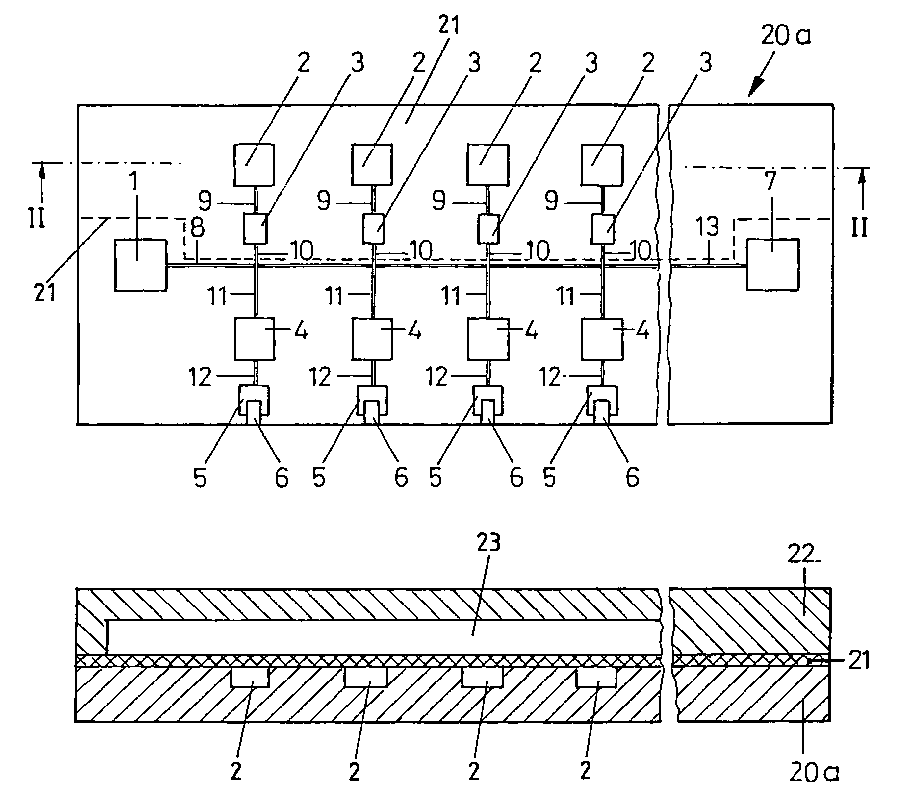
[0056]The first body 20 of a device for parallel metering of a liquid and if necessary for parallel dispensing of a liquid—for example onto a microliter plate—which is shown in FIGS. 1 and 2 has one inlet 1 for the liquid which is to be metered and a number of outlets 6. The inlet 1 and the outlets 6 are connected to one another by a system of channels. The system of channels consists of a main channel 8 and secondary channels 9, 10, 11, 12, one outlet 6 being assigned to each secondary channel 9, 10, 11, 12 (secondary channel arrangements). The system of channels furthermore includes a channel 13 which is routed to a waste collector 7.

[0057]The secondary channels 9, 10, 11, 12 are divided into several channel sections 9, 10, 11, 12. The two channel sections 10, 11 branch off directly from the main channel 8 in opposite directions at a right angle from the main channel 8.

[0058]The channel section 10 of each secondary channel 9, 10, 11, 12 discharges into a first (schematically shown...


PUM

PropertyMeasurementUnit
angleaaaaaaaaaa
angleaaaaaaaaaa
heightaaaaaaaaaa

Abstract

A device for parallel metering of a liquid with the following features:the device has a first body;the first body has a main channel, secondary channels, one inlet and outlets;the main channel is connected to the inlet;the secondary channels are connected to one outlet at a time;the secondary channels are connected to the main channel;the device has at least one first chamber with a first pressure medium;the first body has means for transferring transfer means pressure surges of the pressure medium from a first chamber to the secondary channels;each transfer means is connected to a secondary channel; andat least one means for preventing a fluidic connection between the secondary channels and the chamber is assigned to the transfer means.

Description

BACKGROUND OF THE INVENTION[0001]This invention relates to a device for the parallel metering of a liquid. For this purpose, the device has a first body in which there are a main channel, secondary channels, one inlet, and outlets. The main channel is connected to the inlet, while the secondary channels are connected to one outlet at a time. Furthermore, the secondary channels are connected to the main channel. The first body for delivering the metered liquid has means for transferring pressure surges of a first pressure medium from a first chamber to the secondary channels. Each of these transfer means is connected to a secondary channel.[0002]Such a device is known from document WO 99 / 42805. The device disclosed in this document for the parallel metering of a liquid of the initially mentioned type as the transfer means for transfer of the pressure surges which are imparted to the metered amounts of liquid for emptying the device has small channels which adjoin the secondary channe...

Claims


Application Information

Patent Timeline
Patent Type & Authority Patents(United States)
IPC IPC(8): B41J2/17B41J2/045B01L3/00B01L3/02B05C5/00B05C11/10B41J2/055B41J2/175G01N35/10
CPCB01L3/0241B41J2/17566B01L3/5025B01L3/5027B01L2200/0605B01L2300/0864B01L2400/0406G01N2035/1044B01L2400/06G01N35/1002G01N35/1065G01N35/1072G01N2035/1041B01L2400/0481B01L3/502746
Inventor MULLER-CHORUS, BIRGITPETERS, RALF-PETERBARTOS, HOLGER
Owner BOEHRINGER INGELHEIM MICROPARTS
Learn More