
Cargo compartment organizer

Active Publication Date: 2006-05-02
STEFFENS ENTERPRISES
View PDF10 Cites 14 Cited by
  • Summary
  • Abstract
  • Description
  • Claims
  • Application Information

AI Technical Summary

Benefits of technology

[0011]The present invention provides a utility or toolbox with increased functionality and accessibility. With the conveyor, a user may easily access contents of the toolbox from any side or end of the pick-up bed or cargo bay, regardless of whether the contents shifted in transit or where the contents were placed after the last use. In turn, this reduces the time spent accessing items in the toolbox. Furthermore, the improved shelving of the present invention provides on-demand subdivision of toolbox storage space. It also easily folds out of the way, enabling a user to take full advantage of the storage space without removing the shelving unit altogether from the toolbox.

Problems solved by technology

First, it is common for items stored in a toolbox to shift in transit, particularly if the vehicle traverses a rugged construction site.
This can be frustrating, and usually wastes valuable work time.
Second, a user may place an item in a toolbox on one side of a pick-up bed, and later desire to retrieve the item from the other side of the pick-up bed.
Third, where toolboxes are mounted in pick-ups or vehicles having tall ride heights, a user frequently accesses and uses only the storage space immediately adjacent the pick-up side panels because it is difficult to reach over the side panels and access the center of the toolbox.
Thus, many times the storage capacity of the toolbox is underutilized.
Furthermore, conventional toolbox storage bins frequently make it difficult to store large items, e.g., large power tools, in the toolbox.
Often, the bins are lost or forgotten after removal and therefore no longer useful.
Additionally, debris, such as dirt or nails, collects on the ledges or rails that support the bins, inhibits the movablility of the bins, and damages the interior of the toolbox.

Method used


Image

  • Cargo compartment organizer
  • Cargo compartment organizer
  • Cargo compartment organizer

Examples


Embodiment Construction

I. Overview

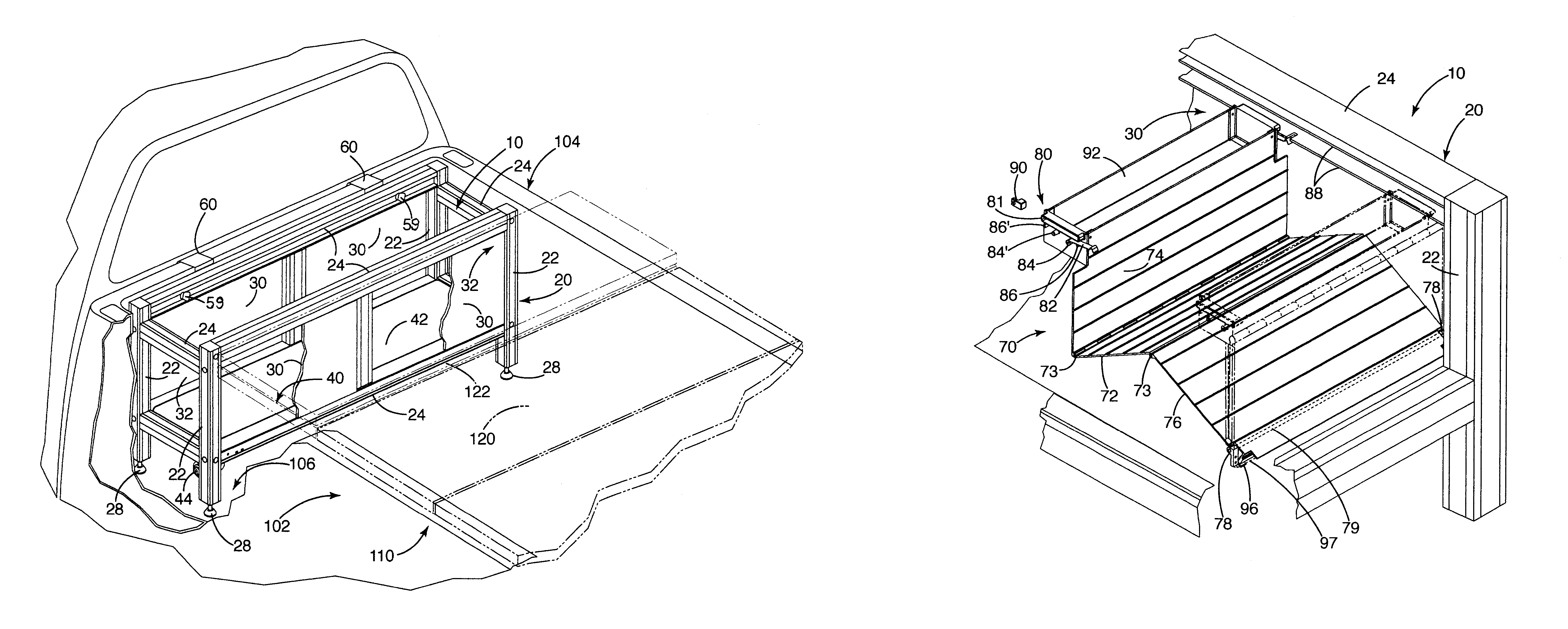
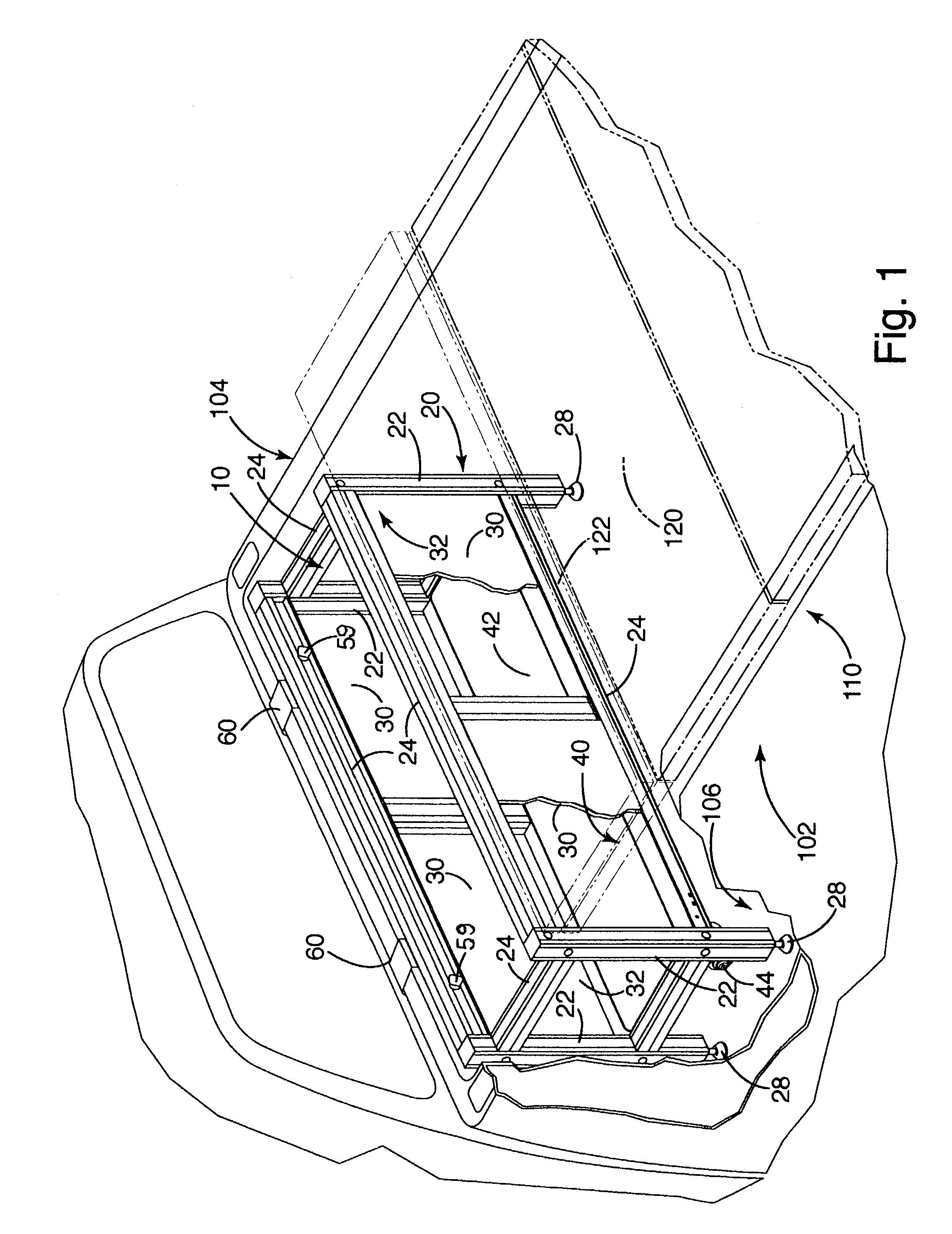
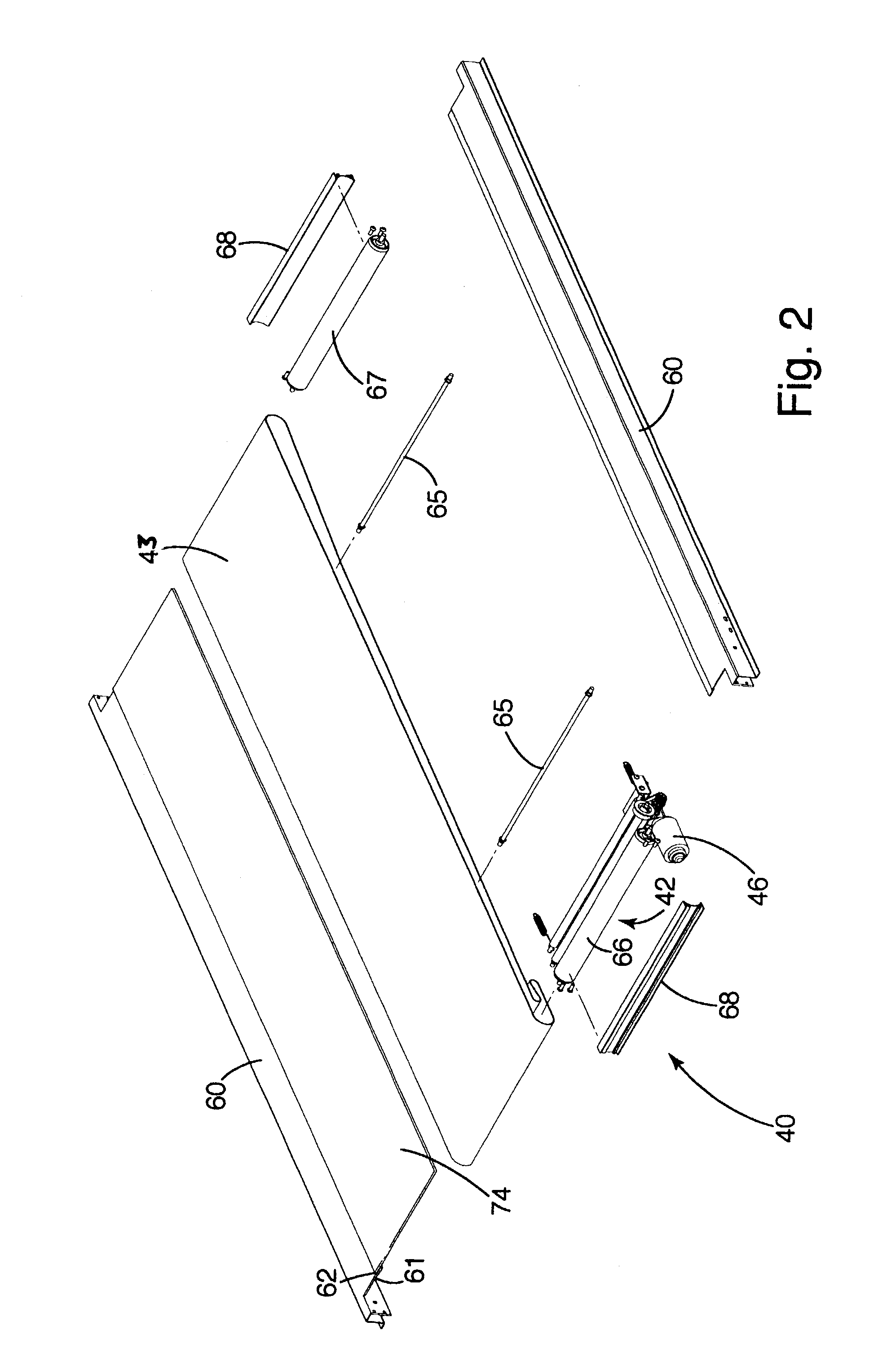
[0020]A toolbox constructed in accordance with a first embodiment of the invention is illustrated in the drawings and generally designated 10. With reference to FIG. 1, the toolbox 10 is shown in conjunction with a conventional folding cargo cover 120, having a panel 122 that opens to provide access to the interior of the toolbox. The toolbox generally includes a frame 20 including multiple vertical support members 22 and horizontal members 24. Sides 30 and ends 32 are secured to the frame to define storage space. A conveyor 40 is mounted to the frame 20, preferably near the bottom of the frame, to form a floor of the toolbox 10.

[0021]With reference to FIGS. 5 and 6, the toolbox includes a fold-out shelving unit 70 mounted in the frame 20 of the toolbox 10. The fold-out shelving 70 includes multiple panels 72, 74, 76, hinged to one another and extendable from a collapsed mode to an extended mode, in which the intermediate panel 72 and pivot panel 76 form a support surface...


PUM


Abstract

A storage box for a cargo bay of a vehicle including a conveyor on which items, e.g., tools and materials, are stored. The conveyor is actuatable to move the items in a pre-selected direction, preferably toward the side or rear of the vehicle cargo bay to provide easy access to the items. In another aspect, the storage box includes fold-out shelving. The shelving includes multiple panels hinged together. A first panel is hingedly connected to an intermediate panel, which is hingedly connected to a second panel, which is pivotally connected to the storage box. The panels are operable in (a) a collapsed mode, where the panels fold substantially vertically against one another, and (b) an extended mode, where the first panel moves outwardly to a substantially vertical position and the intermediate and pivot panel pivot downward to a substantially horizontal position.

Description

BACKGROUND[0001]The present invention relates to toolboxes, and more particularly to toolboxes mounted in the cargo bay of a vehicle.[0002]Pick-up trucks and vehicles having open cargo bays are used extensively for transporting purposes. To protect tools and materials transported in a pick-up bed or an open cargo bay from both theft and the elements, it is common to use a toolbox, also referred to as a “utility box,” that includes an enclosed storage space within which items may be stored. Most toolboxes include a door that provides access to the storage space.[0003]Typically, the toolboxes mount across the pick-up bed between the pick-up bed side panels, or along the side panels. These configurations enable a user to access the toolbox door, by standing along side the side panels, rather than having to enter the pick-up bed.[0004]Often, a toolbox includes one or more storage bins that subdivide the storage space and improve organization within the box. Most storage bins are slidabl...

Claims


Application Information

Patent Timeline
IPC IPC(8): B60N3/12B60R7/08B60R9/00
CPCB60R9/00B60R7/08
Inventor STEFFENS, CHARLES J.SHEERAN, JAMES P.
Owner STEFFENS ENTERPRISES
Learn More