
Sheet material conveying apparatus, recording apparatus and recording system

Inactive Publication Date: 2006-05-02
CANON KK
View PDF7 Cites 20 Cited by
  • Summary
  • Abstract
  • Description
  • Claims
  • Application Information

AI Technical Summary

Benefits of technology

[0052]Now, therefore, the present invention is designed to solve the problems discussed above. It is an object of the invention to provide a sheet material conveying apparatus, a recording apparatus, and a recording system that can prevent the occurrence of double feeding of sheet material, while maximizing the life of the rollers.

Problems solved by technology

Therefore, if the medium has thickness beyond a certain extent, a large conveying power is required for bending it.
This method depends on the friction force between the separation pad and recording medium in order to interrupt the progress of the recording medium for the prevention of double feeding, which makes it difficult to select a separation pad effectively usable for various and many kinds of recording medium.
Thus, there is a limit to the reliability of separation performance.
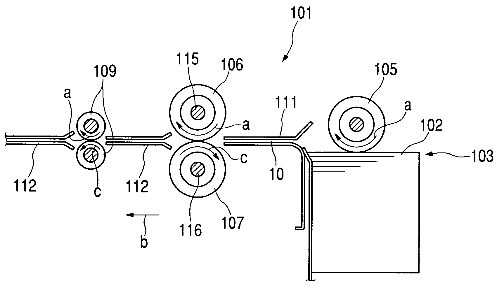
Firstly, as described above, the normal feed area becomes wider if the sheet-feeding conditions are set under the directional condition (toward the upper right in FIG. 12) in which both the pressing force P of the retard roller and the free-running torque Tc of the retard roller are made larger.
However, under such condition, it becomes easier for the recording medium to promote the surface friction of the retard roller, and the retard roller tends to suspend the generation of the free running torque in a short period of time, which may bring about the drawback that the normal feed is disabled eventually.
Particularly, in the case of the ink jet recording apparatus where it is necessary to feed and convey various and many kinds of medium, this harmful effect may take place often.
As described above, it is very difficult to set the sheet-feeding condition under which all the kinds of mediums can be fed and conveyed stably, and the condition should be set at the sacrifice of some other medium, one kind or another.

Method used


Image

  • Sheet material conveying apparatus, recording apparatus and recording system
  • Sheet material conveying apparatus, recording apparatus and recording system
  • Sheet material conveying apparatus, recording apparatus and recording system

Examples


first embodiment

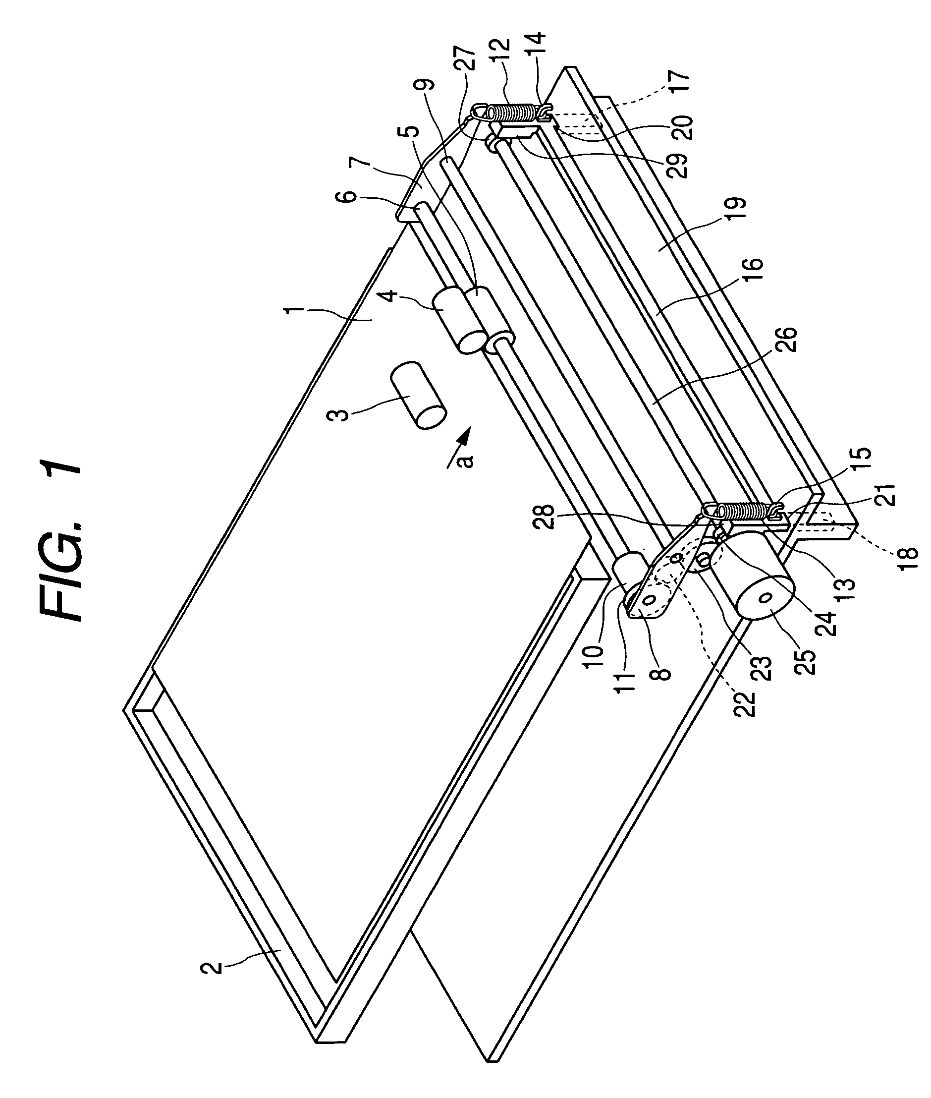
[0082]FIG. 1 is a perspective view that shows the entire body of a recording apparatus in accordance with the present embodiment.

[0083]The sheet-feeding cassette 2, which stores sheets 1 serving as recording medium, is held at a position as shown in FIG. 1 by supporting means (not shown), and approximately 150 sheets 1 can be set in the sheet-feeding cassette 2. A sheet-feeding roller 3 rotates to feed and convey the sheet 1 in the direction indicated by an arrow a by use of driving means and driving transmission means (not shown). Also, a pressure plate (not shown) is arranged in the sheet-feeding cassette 2, which presses all the sheets upward when being fed so that the uppermost sheet 1 is enabled to be in contact with the sheet-feeding roller 3. After this contact, the sheet-feeding roller 3 rotates to feed the sheet 1. A conveying roller 4 rotates in the same direction as the sheet-feeding roller 3 by driving means and driving transmission means (not shown). Rubber is wound aro...

second embodiment

[0106]FIG. 7 is a perspective view that shows the entire body of a recording apparatus in accordance with the present embodiment.

[0107]In FIG. 7, the description will be omitted for the portions having the same functions as those of the first embodiment. Only the different portions will be described.

[0108]The lever 50, which is arranged to protrude from the outer case (not shown) of the recording apparatus, is capable of executing positioning at the left and right positions. Also, an idler gear 51 is arranged to rotate corresponding to the position of the lever 50. As in the case of the first embodiment, both the pressurized contact force of the retard roller 5 against the conveying roller 4 and the rotating-load torque of the retard roller 5 are made variable corresponding to the phase of the idler gear 51. Therefore, it becomes possible to perform sheet feeding stably for various kinds of medium without using an actuator, such as a motor.

third embodiment

[0109]It is a prerequisite to arrange the medium setting provision for a printer driver, which is installed on a host apparatus represented by a personal computer, because it is related to the setting of the ink-discharge amount or the recording mode of an ink jet recording apparatus.

[0110]Therefore, if it is arranged to transmit the information regarding the medium setting at that time, and then, to change the pressurized contact force against the conveying roller 4 and the rotating-load torque of the retard roller 5 in accordance with the information thus transmitted, there is no need for making the changes of the sheet-feeding conditions separately from the setting of other aspects, such as the recording mode. As a result, a recording system having excellent operability can be materialized.

[0111]As described above, in accordance with one aspect of the invention, the sheet material conveying apparatus, which is provided with sheet material holing means for stacking and holding plu...


PUM


Abstract

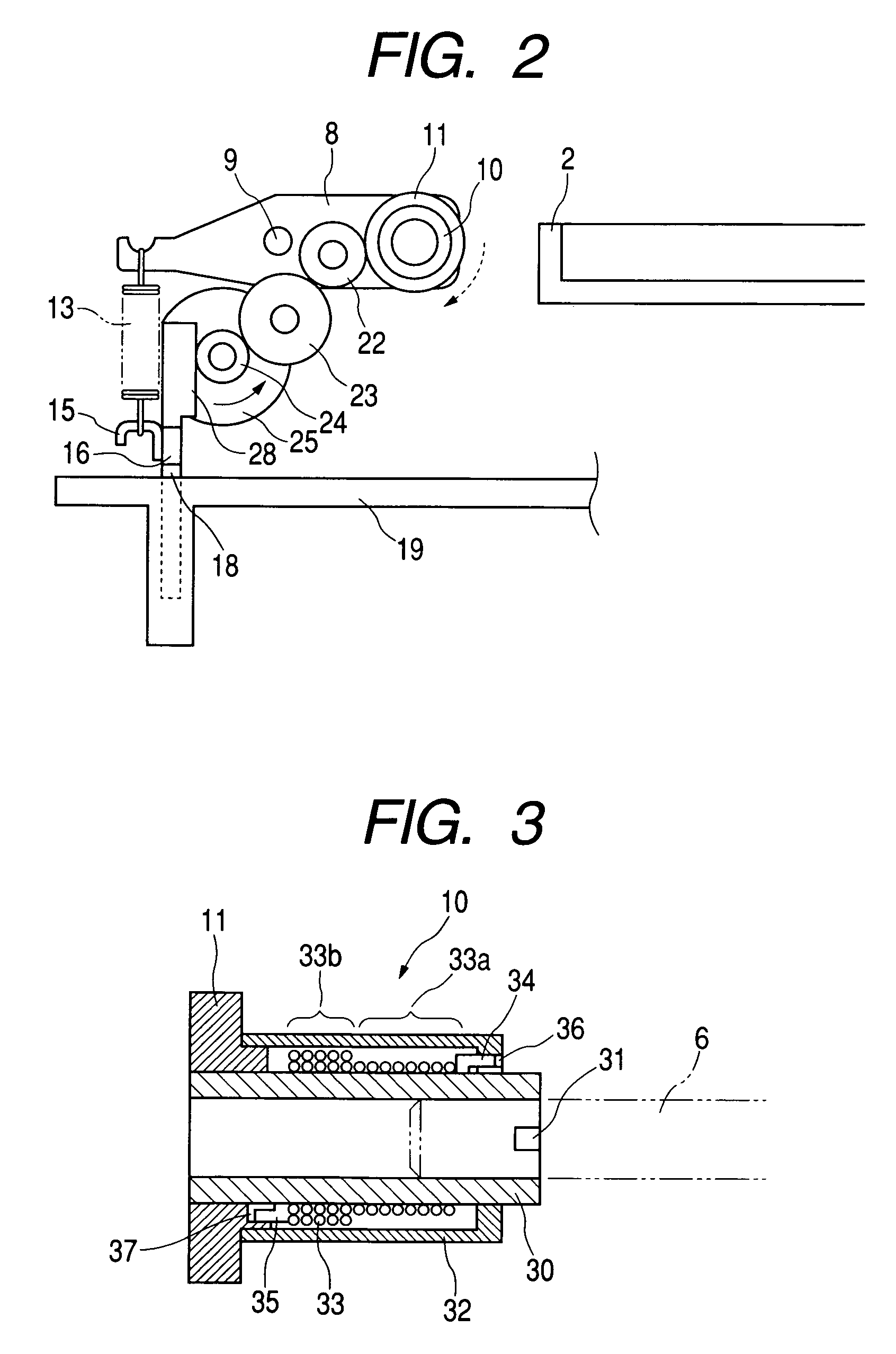
A sheet material conveying apparatus is provided with retard levers for supporting a retard roller shaft, which are rotative centering on the central axis of rotation so as to press the retard roller to a conveying roller. Retard pressing springs are hooked to the spring latches of the retard levers, and the hooks of a slider. When the limiter gear of a torque limiter rotates, the tightening force exerted by a stepped spring against an inner race is caused to change, thus changing the rotating-load torque of the retard roller. A motor enables the limiter gear to rotate, while moving the slider up and down. In this way, it is made possible to change the rotating load torque of the retard roller, while changing the pressurized contact force of the retard roller against the conveying roller. With the structure thus arranged, it is attempted to make the life of rollers longer, and to prevent the occurrence of double feeding of sheet material.

Description

BACKGROUND OF THE INVENTION[0001]1. Field of the Invention[0002]The present invention relates to a sheet material conveying apparatus for conveying sheet material one by one by separating them from those stacked and held. The invention also relates to a recording apparatus that records on the sheet material serving as a recording medium, and a recording system for controlling the recording apparatus as well.[0003]2. Related Background Art[0004]Conventionally, and generally, there have been in wide use the ink jet recording apparatus, the laser beam printer, and the like, which perform recording by means of ink jet recording process or electronic photographing process by conveying only one sheet of recording medium separated from a stack of plural sheets after being set on a sheet-feeding tray or a sheet feeding cassette.[0005]Also, along with the advancement of the ink jet recording process or the electronic photographing process, it has become possible to provide the output in as h...

Claims


Application Information

Patent Timeline
IPC IPC(8): B65H3/52B65H5/06
CPCB65H5/06B65H2403/732B65H2404/143B65H2515/322B65H2551/14B65H2220/04B65H2220/02B65H2515/32
Inventor YAMAMOTO, KOSUKE
Owner CANON KK
Learn More