Image display system, image display apparatus and peripheral devices of image display apparatus

Inactive Publication Date: 2006-04-25
CANON KK
View PDF12 Cites 88 Cited by
  • Summary
  • Abstract
  • Description
  • Claims
  • Application Information

AI Technical Summary

Benefits of technology

[0013]It is an object of the present invention to minimize cables for electrical connections between an image display apparatus and peripheral devices, reduce the size of the entire apparatus and make it possible to adopt a variety of layouts.
[0018]The present invention allows the image display apparatus to be electrically connected to the peripheral devices without cables. This makes it possible to send / receive signals without cables or supply power from one side to another. Moreover, since the mounting positions can be moved along the guide and the first and second electrodes contact at a plurality of positions, it is possible to select a plurality of mounting positions.
[0023]Thus, it is desirable to construct at least part of the above-described guide with a conductive material so that the above-described guide also serves as the first electrode. Furthermore, constructing the entire guide with a conductive material or providing a conductive material along the full length of the guide makes it possible to realize electrical connection of the second electrode at arbitrary mounting positions.
[0025]The present invention has an advantage of being able to change the mounting positions of peripheral devices and this advantage is especially conspicuous when the display apparatus has a large screen, or more specifically when the width across corners of the display plane is 20 inches or more. Furthermore, this becomes a particularly conspicuous advantage when the width across corners is 30 inches or more or 40 inches or more. The maximum width across corners may be about 100 inches.
[0026]Furthermore, the present invention can also adopt a spherical shape for the above-described first and second electrodes. This makes it possible to reduce friction and implement smooth movement of the mounting positions.
[0027]In this case, it is also possible to provide an elastic material to support the above-described spherical first electrode or second electrode. This makes the contact between both electrodes more reliable.

Problems solved by technology

Mounting the image display apparatus in such a conventional configuration on the wall requires a space to pass cables on the back and installing the image display apparatus separate from the wall for that space ends up sacrificing the intended space-saving feature, particularly in the case of a thin type image display apparatus.
Moreover, the exposure to the wall surface of connection cables between the image display apparatus and other devices, for example, a video cassette recorder looks awful.
In addition, when the speakers are attached or detached, the image display apparatus needs to be taken off the wall, which is problematic in terms of maintenance.
On the other hand, in the case where the image display apparatus is installed on a stand, it is also necessary to secure a space for housing various cables on the back and separate the stand from the wall surface, which sacrifices the space-saving feature again.
Moreover, cables of various voltages and frequencies intertwined on the back may adversely affect the electrical circuit and even deteriorate the quality of images.
However, connections between an image display apparatus and its peripheral devices will be more and more complicated in order to conform to new systems and there is also a fear of wire connection errors.

Method used


Image

  • Image display system, image display apparatus and peripheral devices of image display apparatus
  • Image display system, image display apparatus and peripheral devices of image display apparatus
  • Image display system, image display apparatus and peripheral devices of image display apparatus

Examples


first embodiment

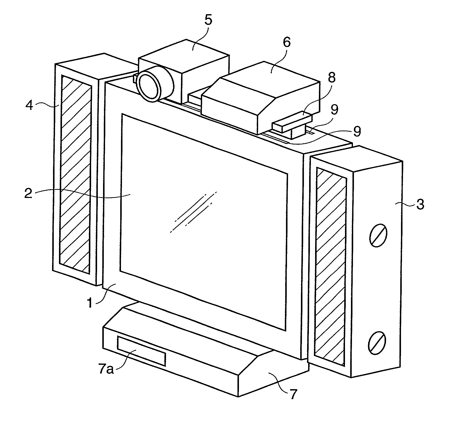
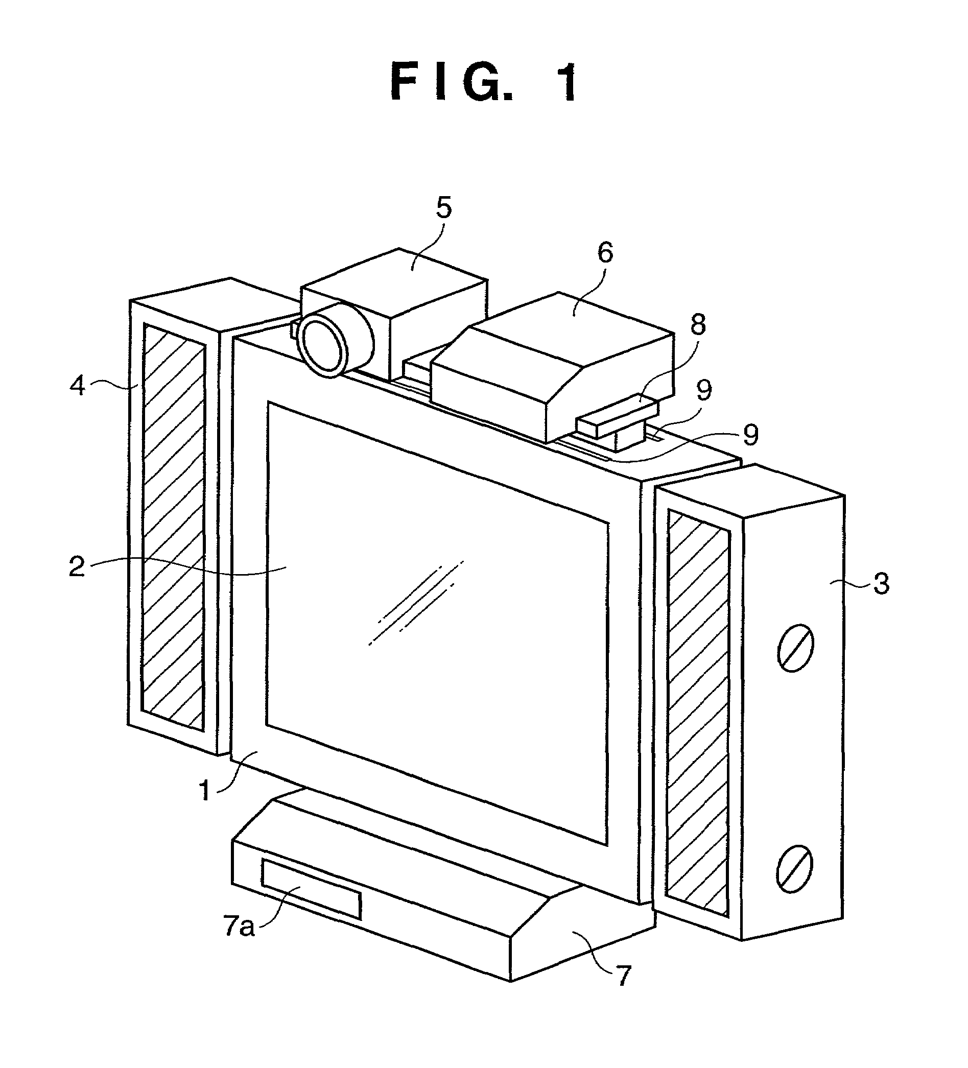
[0052]FIG. 1 is an external view of an image display system according to a first embodiment of the present invention.

[0053]This image display system includes an image display apparatus 1 having an image display section 2, peripheral devices that can be freely attached to or detached from the image display apparatus 1, that is, speaker units 3 and 4, a camera 5, a set top box 6 that incorporates a signal conversion circuit having the function of inputting / outputting various signals, and a stand unit 7 that incorporates a recording / reproduction device.

[0054]Examples of the image display apparatus 1 are thin type image display apparatuses using a display panel such as SED, PDP, liquid crystal, EL. The stand unit 7 not only supports the image display apparatus 1 but also loads information of a recording medium inserted from a recording medium insertion section 7a and outputs it as an image signal or sound signal to the image display apparatus 1.

[0055]Furthermore, in FIG. 1, rails 8 havi...

second embodiment

[0089]FIG. 5 is an external view of an image display system according to a second embodiment of the present invention and configurations with the same reference numerals as those in the above-described first embodiment denote the same configurations. The system according to this embodiment includes speaker units 3 and 4 on the left and right sides and a center speaker unit 200 on top of the image display apparatus 1. Provision of the center speaker unit 200 can improve an acoustic characteristic of sound output to the audience.

[0090]Linear openings 30 are provided on top, bottom and right and left sides of the image display apparatus 1. Reference numeral 31 denotes the right and left sides of the image display apparatus 1, which are sides closely contacting the speaker units 3 and 4. Reference numeral 201 denotes the top face of the image display apparatus 1, which is a side closely contacting the center speaker unit 200.

[0091]Connection holes 32 and 33 are holes for electrical conn...

third embodiment

[0123]FIG. 7 is an external view of an image display system according to a third embodiment of the present invention and configurations with the same reference numerals as those in the above-described first and second embodiments denote the same configurations.

[0124]A rail section 50a has a quasi-[ ]-shaped section and is rail-shaped and makes up part of the frame with four sides of the image display apparatus 1. This rail section 50a is molded through metal extrusion, cut to a predetermined length and formed into a quasi-rectangle. The rail section 50a is formed on all the four sides that make up the frame of the image display apparatus 1.

[0125]A rail insertion section 51 is shaped so that it is engaged with and slid along the rail section 50a of the image display apparatus 1, and provided on the left and right speaker units 3 and 4. A fixing screw thrusting section 52b is provided inside an opening in the center of the rail insertion section 51 and can zoom in and out from the abo...


PUM


Abstract

An image display system has an image display apparatus and a peripheral device that can be mounted on the image display apparatus. The image display apparatus includes a first electrode for electrically connecting the image display apparatus and peripheral device, and the peripheral device includes a second electrode for electrically connecting the image display apparatus and peripheral device. These electrodes are placed so as to have contact with one another when the peripheral device is mounted on the image display apparatus. In addition, the image display system moves the mounting position of the peripheral device on the image display apparatus as appropriate. The system minimizes cables used for electrical connections between the image display apparatus and peripheral devices, makes the apparatus compact and allows adoption of a variety of layouts.

Description

FIELD OF THE INVENTION[0001]The present invention relates to an image display apparatus such as a TV set, and more specifically, to a structure of connection between an image display apparatus and peripheral devices.BACKGROUND OF THE INVENTION[0002]Thin, flat type image display apparatuses such as display apparatuses using electron emission elements, display apparatuses using plasma discharge, display apparatuses using LCD and display apparatuses using a vacuum fluorescent display are used for applications such as TV, computer terminals, advertising media and signs.[0003]What has been a focus of attention in recent years is a wall-mounting type TV set with a screen size of 40 inches or more, and whether the screen size is 40 inches or 50 inches, one of their features is the space saving feature with the screen display section having a depth of 100 mm or less.[0004]On the other hand, such an image display apparatus comes with a variety of peripheral devices such as an image / sound rep...

Claims


Application Information

Patent Timeline
IPC IPC(8): H04N5/64G06F1/16
CPCG06F1/1601G06F1/1605G06F1/1607H04N5/64H04N5/642Y10S248/918G06F2200/1612
Inventor TAJIMA, HISAO
Owner CANON KK
Why Eureka
Try Eureka