Eureka AIR delivers breakthrough ideas for toughest innovation challenges, trusted by R&D personnel around the world.

Hybrid inductive-capacitive charge pump with high diode driving capability

a charge pump and diode technology, applied in the direction of electric variable regulation, instruments, apparatus without intermediate ac conversion, etc., can solve the problem of asymptotic voltage reached, and achieve the effect of high diode driving capability and avoiding threshold loss

Inactive Publication Date: 2006-04-25
STMICROELECTRONICS SRL
View PDF9 Cites 13 Cited by
  • Summary
  • Abstract
  • Description
  • Claims
  • Application Information

AI Technical Summary

Benefits of technology

[0004]The aim of the present invention is to provide a hybrid inductive-capacitive charge pump with high diode driving capability, which allows to avoid the threshold loss that is typical of MOS transistors of known circuits.
[0006]Another object of the present invention is to provide an inductive-capacitive charge pump that allows to reduce the number of boost capacitors to be driven, consequently achieving a reduction in the power in input to the circuit and an increase in efficiency.
[0008]A still further object of the present invention is to provide a hybrid inductive-capacitive charge pump that allows to optimize the power dissipated by the step-up device.
[0009]Another object of the present invention is to provide a charge pump circuit that is highly reliable, relatively simple to manufacture and at competitive costs.

Problems solved by technology

One significant limitation on the asymptotic voltage reached by an ordinary charge pump circuit provided as described above is due to the loss of a threshold voltage on each one of the MOS transistors that constitute the circuit.

Method used


Image

  • Hybrid inductive-capacitive charge pump with high diode driving capability
  • Hybrid inductive-capacitive charge pump with high diode driving capability
  • Hybrid inductive-capacitive charge pump with high diode driving capability

Examples


Embodiment Construction

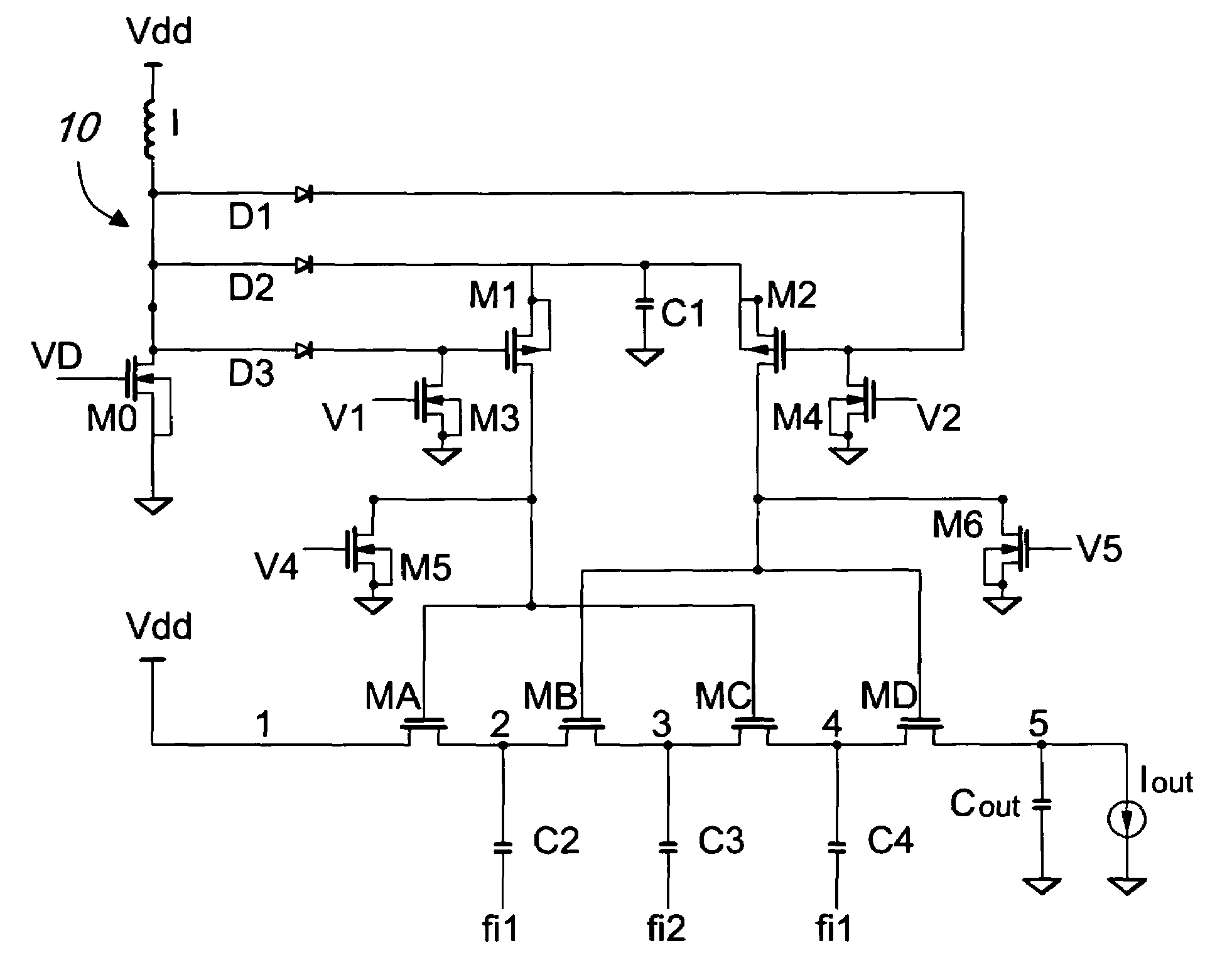
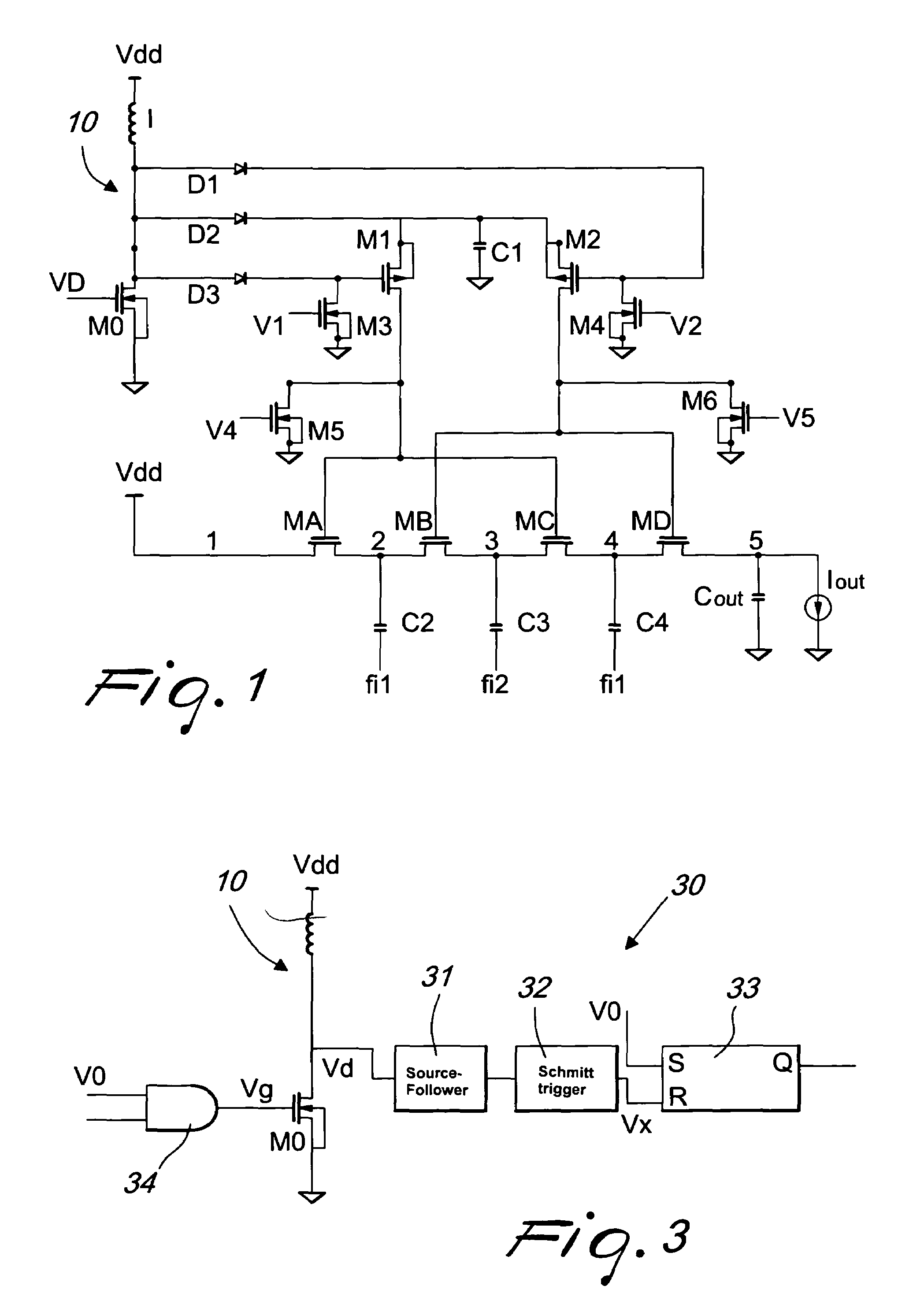
[0015]With reference to the figures cited above, and initially with reference to FIG. 1, the inductive-capacitive charge pump circuit comprises a step-up converter, which comprises a branch designated by the reference numeral 10 in FIG. 1; the converter is mainly composed of an inductor I, which is coupled to the power supply Vdd of the converter and to the drain terminal of a MOS transistor M0 (termed “step-up transistor”). The step-up transistor M0 is of the n-channel type and can be activated by a signal V0 applied to its control terminal (gate terminal).

[0016]The inductive branch 10 of the converter can further comprise means for the automatic adjustment of the power delivered by the circuit, shown in FIG. 3.

[0017]The automatic power adjustment means comprise means 30 for reading a voltage of the branch 10 and for switching off the step-up transistor when said voltage exceeds a certain threshold value. In practice, the means 30 consist of a fedback system, which has a source-fol...


PUM


Abstract

A hybrid inductive-capacitive charge pump provided with a driving stage that comprises a step-up converter and a buffer capacitor, and a cascade of charge pump stages; the first stage of the stage cascade is connected to a power supply and the last stage of the stage cascade is connected to an output of the charge pump circuit; the charge pump circuit comprises elements for activating alternately the charge pump stages, transferring charge from one stage of the cascade to the next stage of the cascade, each stage of the cascade of charge pumping stages comprising a pass transistor and a capacitor.

Description

BACKGROUND OF THE INVENTION[0001]The present invention relates to a hybrid inductive-capacitive charge pump with high diode driving capability.[0002]As is known, a charge pump circuit is conventionally provided by means of diode-connected MOS transistors. One significant limitation on the asymptotic voltage reached by an ordinary charge pump circuit provided as described above is due to the loss of a threshold voltage on each one of the MOS transistors that constitute the circuit.[0003]Moreover, the thresholds rise toward the last stages of the circuit, where the voltage between the source and the bulk assumes high values and the body effect becomes more conspicuous.SUMMARY OF THE INVENTION[0004]The aim of the present invention is to provide a hybrid inductive-capacitive charge pump with high diode driving capability, which allows to avoid the threshold loss that is typical of MOS transistors of known circuits.[0005]Within this aim, an object of the present invention is to provide a...

Claims


Application Information

Patent Timeline
IPC IPC(8): G05F3/02H02M3/07H02M3/155
CPCH02M3/155H02M3/073
Inventor CARMINA, MICHELECOLALONGO, LUIGIKOVACS VAJNA, ZSOLT MIKLOS
Owner STMICROELECTRONICS SRL
Why Eureka
Eureka Blog
Learn More