
Fastener having improved penetration capability

a technology of fasteners and piercings, which is applied in the direction of fastening means, nails, mechanical equipment, etc., can solve the problems of lack of pull-out resistance of hardened pins when installed in light-gauge materials, time-consuming and fatuous installation of helical threaded fasteners, and inability to pull the substrate and the workpiece together

Inactive Publication Date: 2006-04-25
EVENING STAR INVESTMENTS L L C
View PDF22 Cites 9 Cited by
  • Summary
  • Abstract
  • Description
  • Claims
  • Application Information

AI Technical Summary

Problems solved by technology

However, installation of helical threaded fasteners has proven time-consuming and fatiguing to the installer.
Additionally, the thinness of these metals is such that is creates situations where there is insufficient material to provide a friction-lock for current state-of-the-art pins.
Whether they incorporate barbs, protrusions, undercuts, cross-hatching or spiral threads, these hardened pins lack withdrawal resistance when installed in these light-gauge materials.
Additionally, they lack the ability to pull the substrate and the work piece together to close the gap between them caused by the deflection when the metal substrate is of light-gauge metal.
The provision of such ribs or side flanges dramatically increases driving forces necessary for installation of the nail.
However, when denser laminates (i.e., gypsum board, plywood, oriented-strand board, cement board) are being fastened to a metal substrate, driving forces encountered are of such nature as to possibly cause incomplete installation.
When a commercial pneumatic tool is used for power installation, these added driving forces are enough to “stall-out” the tool.
It has also been discovered that power installation of a fastener can exceed the driving forces available from the power tool if the maximum thickness of the body is engaged at the beginning of the penetrating point.
Any protuberance beyond the surface of the body, except for the tine, acts as driving resistance and can adversely affect proper installation.

Method used


Image

  • Fastener having improved penetration capability
  • Fastener having improved penetration capability
  • Fastener having improved penetration capability

Examples


Embodiment Construction

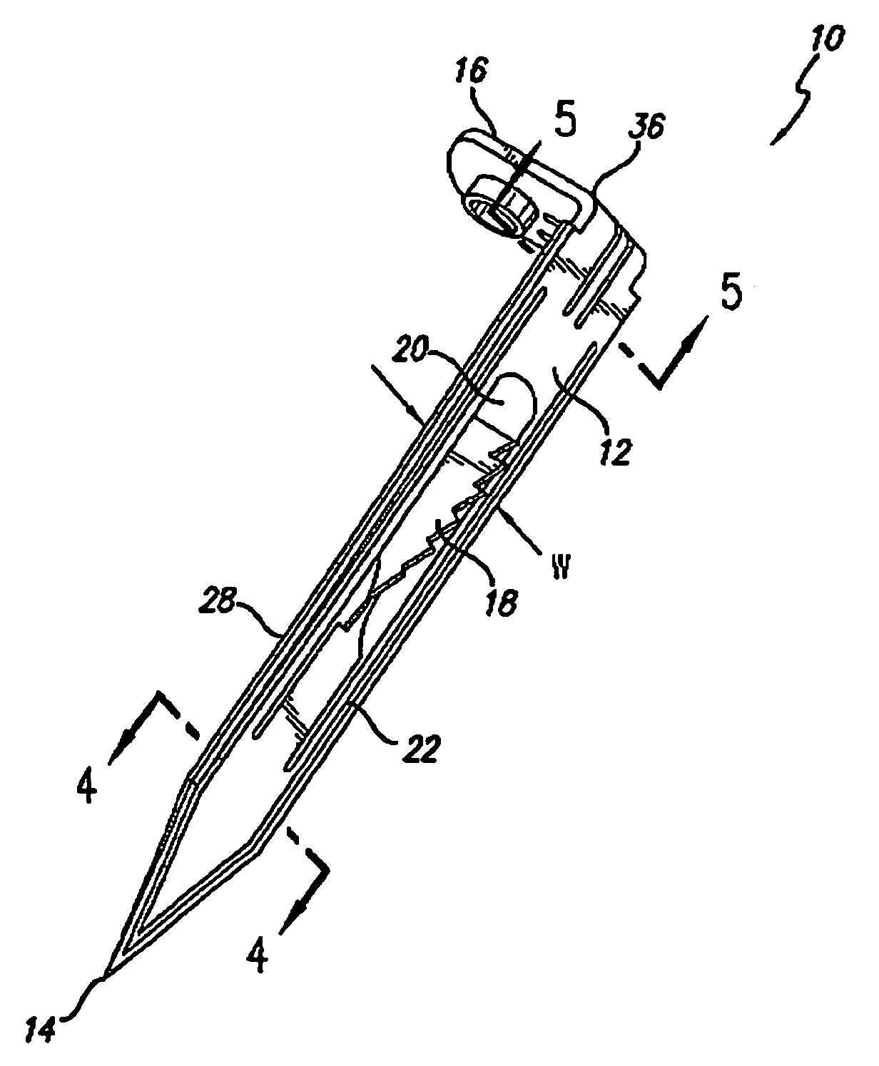
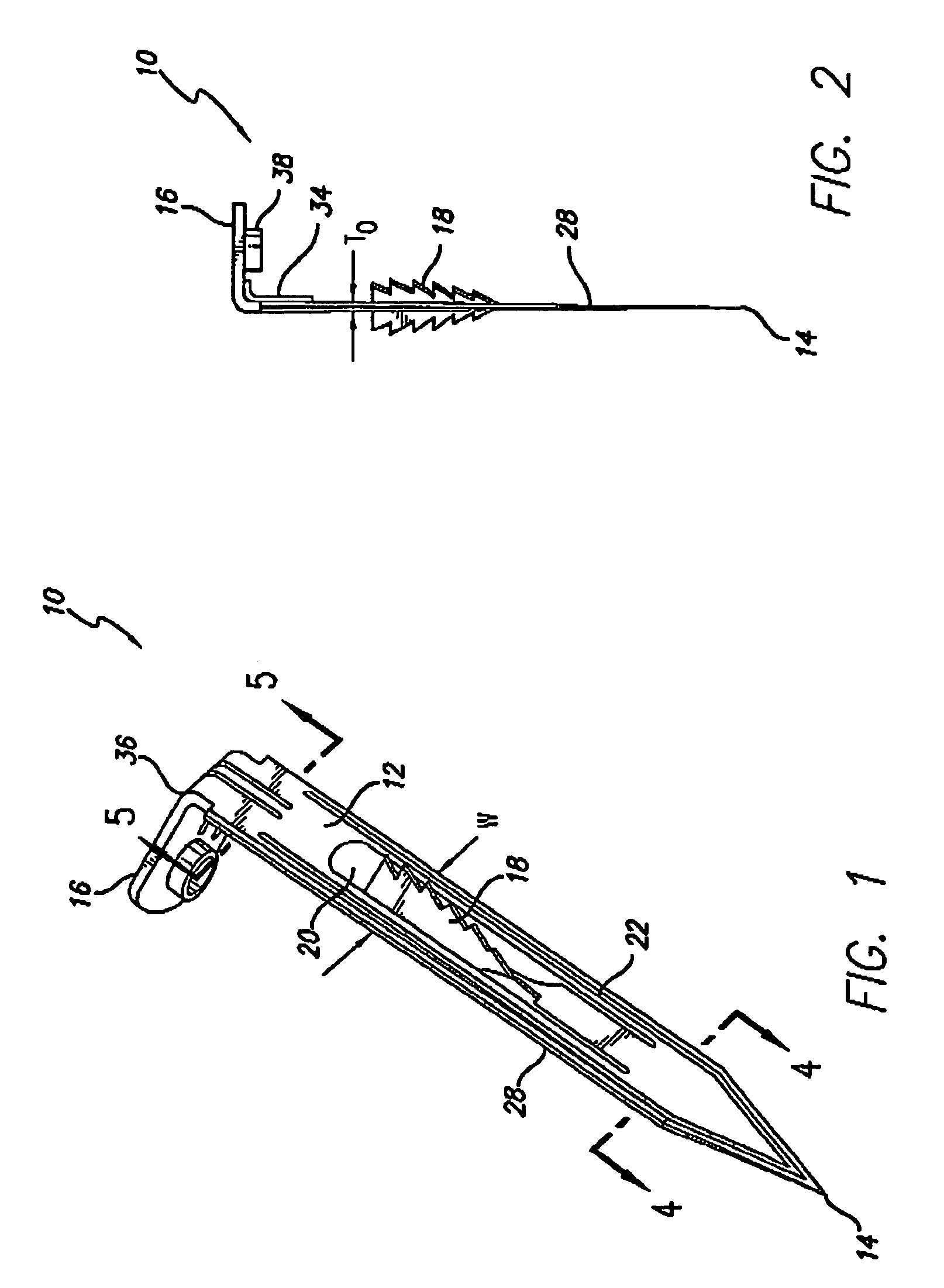
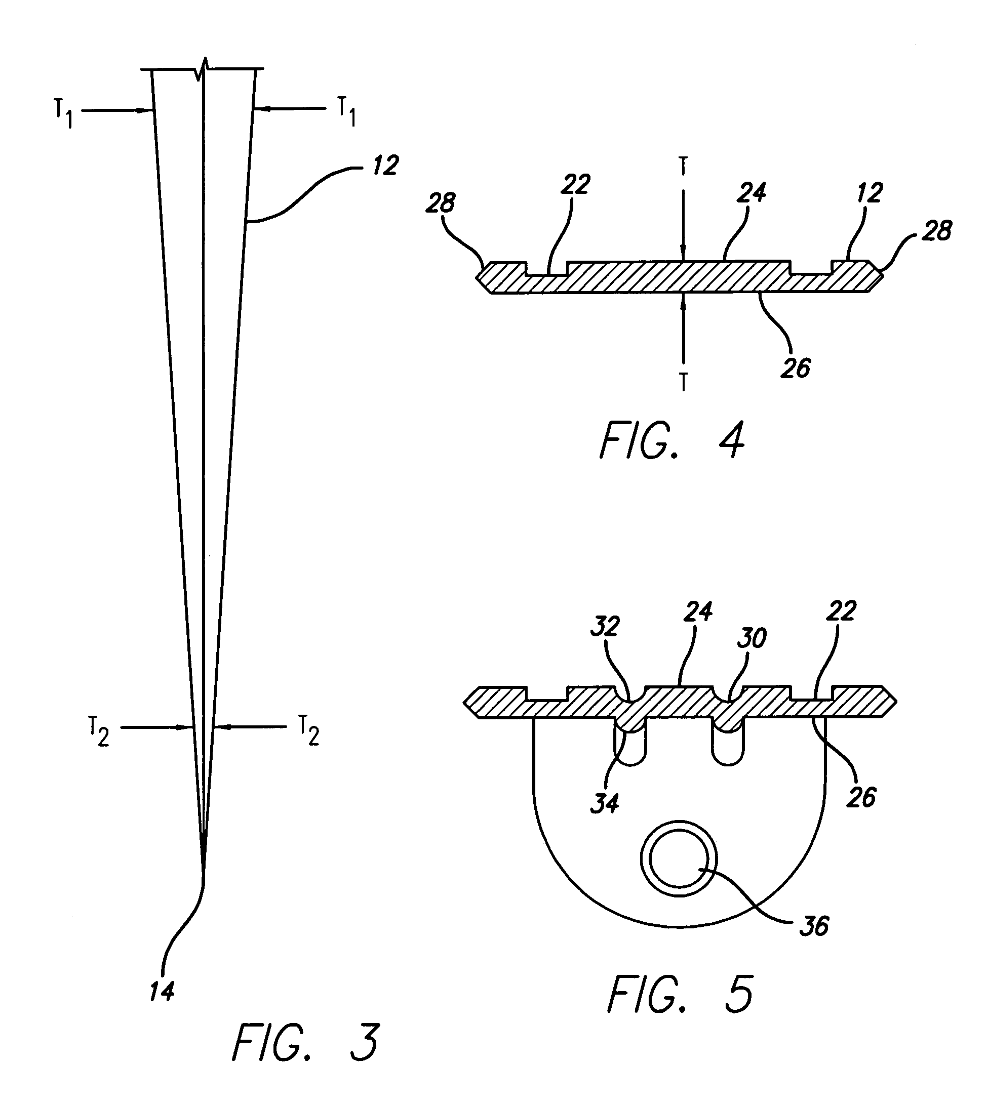
[0014]A fastener constructed in accordance with the present invention eliminates substantially all protrusions from that portion of the body of the fastener which penetrates the metallic substrate to thus minimize the friction involved as the fastener penetrates the metallic substrate. In addition, the thickness dimension of the body of the fastener is formed to have a “wedge” profile with the thinnest part of the wedge nearest the penetrating point. Such a profile reduces the initial forces required to form the aperture in the metal substrate which in turn, allows the forces generated by the power tool to provide sufficient velocity to drive the fastener through the work piece and through the metal substrate to a position such that the substrate and the work piece can be clamped together.

[0015]These and other features of the fasteners in accordance with the present invention are illustrated in the drawings to which reference is hereby made. As is shown, in FIG. 1, the fastener 10 i...


PUM


Abstract

A metal piercing fastener having an elongated flat body having first and second surfaces with a heat at one end and a piercing point at the other. The thickness dimension of the flat body is greater proximate the head proximate the point. The first and second surfaces of the body are devoid of protrusions extending outwardly therefrom.

Description

RELATED APPLICATIONS[0001]This application is a continuation-in-part of U.S. application Ser. No. 09 / 724,333, which was filed on Nov. 28, 2000, now U.S. Pat. No. 6,659,700 for “METAL PIERCING FASTENER” by the Applicants of this application and is assigned to the same Assignee.FIELD OF THE INVENTION[0002]The present invention relates generally to fasteners and more particularly to a metal piercing fastener for securing one or more metal / non-metal layers to at least one metal layer and retaining the secured layers in their positions permanently under adverse conditions.BACKGROUND OF THE INVENTION[0003]Fastener designs for securing work pieces together, such as, for example, a top laminate non metal work piece to a bottom light-gauge metal substrate (18 gauge and thinner) or alternatively, a light-gauge metal work piece to light-gauge metal substrate have generally been accomplished by threaded fasteners. The helical design of the thread has been successful in pulling the top laminate ...

Claims


Application Information

Patent Timeline
Patent Type & Authority Patents(United States)
IPC IPC(8): F16B15/00F16B15/06F16B15/08
CPCF16B15/0015F16B15/06F16B15/08
Inventor FARRELLFARRELL, MICHAEL
Owner EVENING STAR INVESTMENTS L L C
Learn More