
Air bag apparatus for a small size vehicle

Active Publication Date: 2006-04-25
HONDA MOTOR CO LTD
View PDF15 Cites 10 Cited by
  • Summary
  • Abstract
  • Description
  • Claims
  • Application Information

AI Technical Summary

Benefits of technology

[0007]The present invention has been made in view of the above-described circumstance. It is an object of the present invention to provide an air bag apparatus for a small size vehicle, which assures a wide range of inflation and expansion of an air bag and can be applied to a conventional small size vehicle without the necessity of significant design changes to accommodate the air bag.
[0009]With the above configuration, when the plurality of air bags are inflated and expanded, all of the air bags are connected to each other by the connection mechanism and are expanded over a wide range. Thus, the function of a large air bag can be secured by the plurality of small air bags while a wide range of expansion can be covered by the plurality of air bags to constrain the driver effectively. In addition, since each of the air bags may be of a small size, it is easy to assure the space for accommodating the air bags, and the air bag apparatus can be applied to a conventional small size vehicle without the necessity of significant design changes to accommodate the air bags.
[0010]Furthermore, according to a second aspect of the present invention, the air bag apparatus for a small size vehicle is provided, wherein the connection mechanism connects a pair of left and right air bags accommodated in a folded state on the opposite left and right sides of the instrument panel to each other. The connection mechanism is securely fastened to the vehicle body. With the above configuration, leftward and rightward movements of the pair of left and right inflated and expanded air bags can be restricted by the connection mechanism, which is securely fastened to the vehicle body to constrain the driver effectively.

Problems solved by technology

If a single air bag is used such that it is expanded to a wide range, then it is difficult with a conventional small size vehicle such as a motorcycle to assure a space for accommodation of a large size air bag.
Accordingly, it is sometimes necessary to effect significant design changes to accommodate such an air bag.

Method used


Image

  • Air bag apparatus for a small size vehicle
  • Air bag apparatus for a small size vehicle
  • Air bag apparatus for a small size vehicle

Examples


Embodiment Construction

[0019]In the following, an embodiment of the present invention is described in connection with an example of the present invention shown in the accompanying drawings. It should be noted that the same reference numerals have been used to identify the same or similar elements throughout the several views.

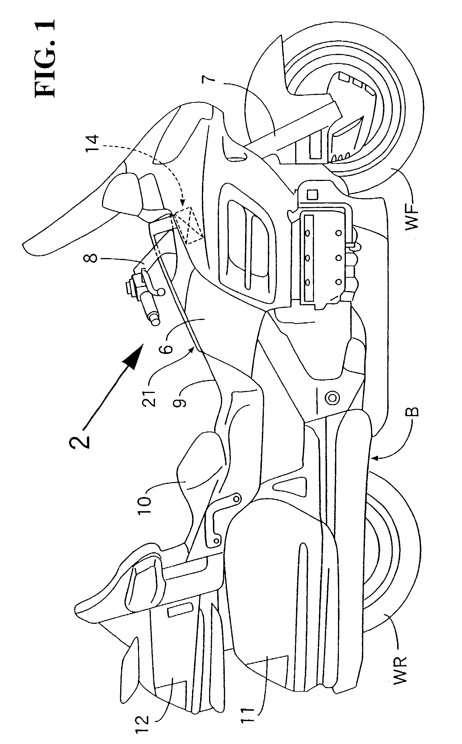
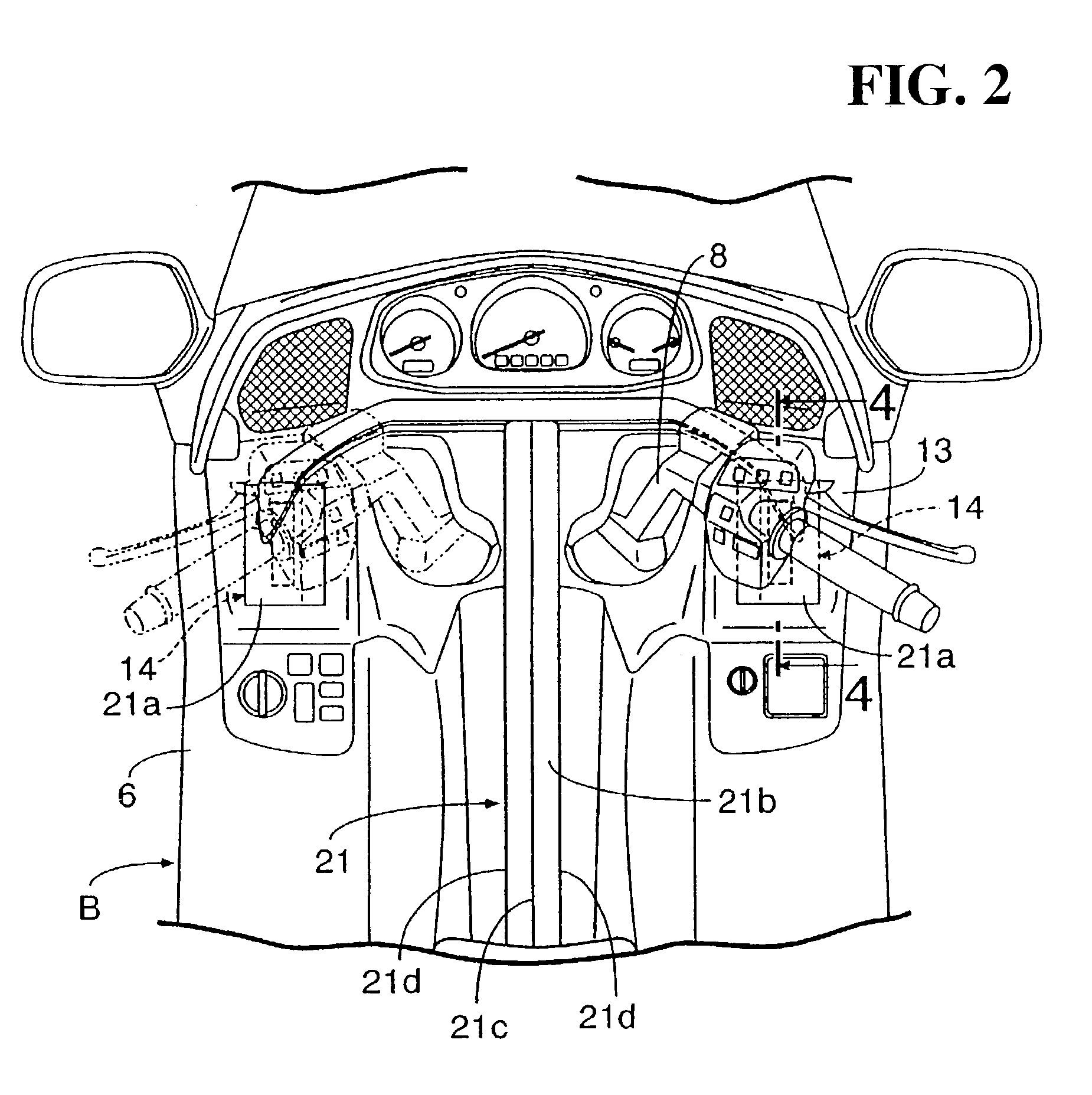
[0020]FIGS. 1 to 6 show an example of the present invention. FIG. 1 is a side elevation of a motorcycle. FIG. 2 is a view in a direction indicated by an arrow 2 in FIG. 1. FIG. 3 is a view corresponding to FIG. 2 but in a state wherein a steering handle bar is omitted for clarity. FIG. 4 is an enlarged sectional view taken along line 4—4 of FIG. 2. FIG. 5 is a side elevational view corresponding to FIG. 1 but in a state wherein the air bags are inflated and expanded. FIG. 6 is a view in a direction of an arrow 6 in FIG. 5.

[0021]Referring first to FIG. 1, a body B of the motorcycle V includes a body frame (not shown), which is covered with a body cover 6 made of a resin material. A fro...


PUM


Abstract

To provide an air bag apparatus for a small size vehicle, wherein a seat for a driver is provided at a rear portion of a vehicle body and an instrument panel, which a driver on the seat can visually observe is provided at a front portion of the vehicle body. The air bag apparatus assures a wide range of inflation and expansion of an air bag and can be applied to a conventional small size vehicle without a significant design change. A plurality of air bags which can constrain a driver on a seat from a forward direction are connected to each other by a connection mechanism and are accommodated in a folded state in an instrument panel.

Description

CROSS-REFERENCE TO RELATED APPLICATIONS[0001]This nonprovisional application claims priority under 35 U.S.C. § 119(a) on Patent Application No. 2002-118664, filed in Japan on Apr. 22, 2002, the entirety of which is incorporated herein by reference.BACKGROUND OF THE INVENTION[0002]1. Field of the Invention[0003]The present invention relates to a small size vehicle, wherein a seat for a driver is provided at a rear portion of a vehicle body and an instrument panel, which a driver on the seat can visually observe, is provided at a front portion of the vehicle body. More particularly, the present invention relates to improvements in an air bag apparatus provided in a small size vehicle.[0004]2. Description of Background Art[0005]Conventionally, in a motorcycle disclosed in the official gazette of, for example, Japanese Patent Laid-Open No. 2001-219884, a single air bag in a folded state is disposed forwardly of a handle bar or the motorcycle.[0006]In order to effectively constrain the d...

Claims


Application Information

Patent Timeline
IPC IPC(8): B60R21/16B60R21/00B60R21/20B60R21/205B60R21/217B60R21/233B60R21/2338B62J1/12B62J27/00B62J99/00
CPCB60R21/20B60R21/2338B62J27/00B60R21/2171B60R2021/23107B60R2021/23386B60R2021/0088B62J27/20
Inventor KURATA, NORIHIROYAMAZAKI, TAKESHIKUROE, TAKESHI
Owner HONDA MOTOR CO LTD
Learn More