Eureka AIR delivers breakthrough ideas for toughest innovation challenges, trusted by R&D personnel around the world.

Operator control station for controlling different work machines

a technology for operating control stations and work machines, applied in the direction of movable seats, transportation and packaging, tractors, etc., can solve the problems of limiting the engineers' ability to enhance the operator's comfort, operator vibration and jarring, and operator inability to easily monitor all operating conditions in all seat positions

Inactive Publication Date: 2006-04-25
CATERPILLAR INC
View PDF38 Cites 56 Cited by
  • Summary
  • Abstract
  • Description
  • Claims
  • Application Information

AI Technical Summary

Benefits of technology

[0010]In yet another aspect of the present invention, a plurality of different work machines include interchangeable operator control stations.
[0011]In yet another aspect of the present invention, there is a method of installing an interchangeable operator control station, incl

Problems solved by technology

First, as work machines become more complex, work machine operators increasingly need the ability to vary their viewing perspective to more effectively operate implements of the work machines.
The operator may be in a cab of the work machine for long periods of time and may be subjected to vibrations and jarring caused by rough terrain and the operation of the work machine.
Thus, the operator cannot easily monitor all operating conditions while in all seat positions.
Besides limiting the operator's ability to control and monitor the work machine from all positions, the stationary controls and panels also limit the engineers ability to enhance the operator's comfort.
An active suspension and / or ergonomic strategies that move the operator's seat to compensate for the vibrations caused by the machine or uneven ground are not easily utilized because they may alter the position of the operator with respect to the stationary controls and panel.
The stationary controls and panels also limit the space the operator has in the cab.
In addition, the Grigg operator control station is designed for a specific type of work machine, a Load-Haul Dump vehicle, and thus, is limited in its application.
Thus, the operator may find it difficult to learn and operate different work machines or different sizes of the same type of work machine.

Method used


Image

  • Operator control station for controlling different work machines
  • Operator control station for controlling different work machines
  • Operator control station for controlling different work machines

Examples


Embodiment Construction

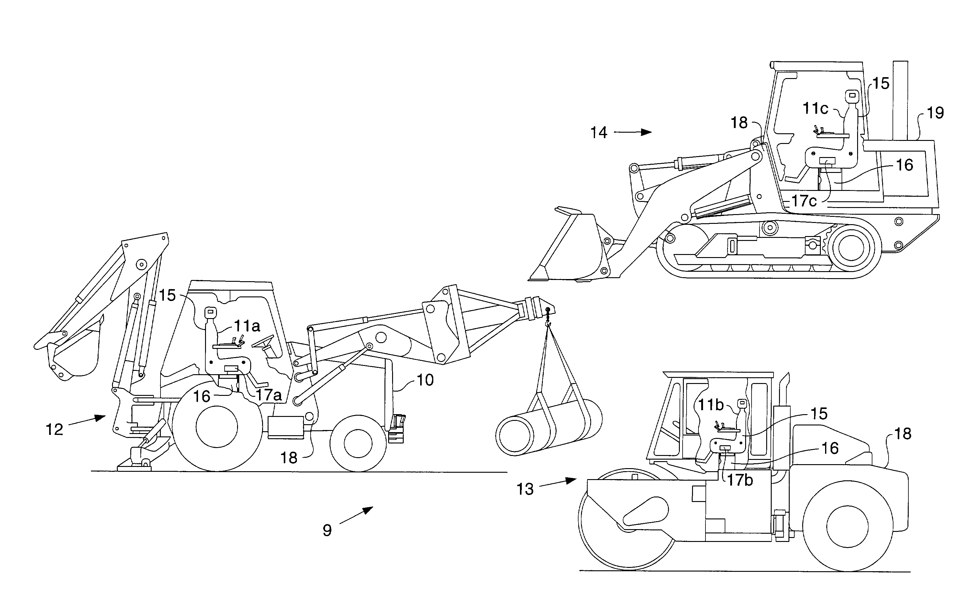
[0016]Referring to FIG. 1, there is shown a representation of a plurality of different work machines 9, each including an interchangeable operator control station 11a, 11b, 11c. It should be appreciated that the term “different work machines” is referring to work machines that are dissimilar due to each work machine's type and / or size, and not simply because each work machine is a separate, but identical, machine. The plurality of work machines 9 includes work machines of different types, including, but not limited to a backhoe loader 12, a vibratory drum compactor 13, and a track-type tractor 14. Although the interchangeable operator control stations 11a, 11b, 11c are shown installed in the backhoe loader 12, the vibratory drum compactor 13, and the track-type tractor 14, it should be appreciated that the interchangeable operator control station could be installed in virtually any type or size of work machine, regardless of the implements of the work machine or vehicle. For example...


PUM


Abstract

In order to enhance an operator's ability to control a work machine, an operator control station includes a seat assembly that is moveably mounted to a body of the work machine. The operator can control, at least in part, primary operator controllable aspects of the work machine by manipulating work machine operating controls attached to move with the seat assembly. The operator can monitor a work machine operating condition, at least in part, via a work machine operating condition display panel also attached to move with the seat assembly. In addition, the operator control station is interchangeable among a plurality of work machines of different types and sizes.

Description

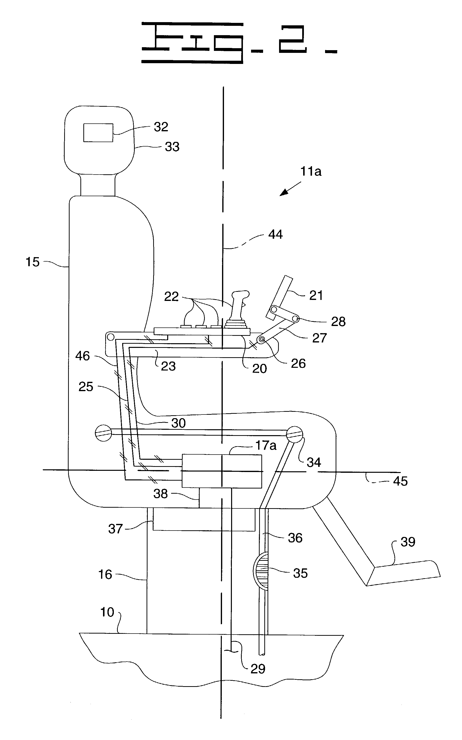
TECHNICAL FIELD[0001]The present invention relates generally to operator control stations, and more specifically to an interchangeable operator control station for use in a plurality of different work machines.BACKGROUND[0002]When designing operator control stations for work machines, engineers have multiple objectives. First, as work machines become more complex, work machine operators increasingly need the ability to vary their viewing perspective to more effectively operate implements of the work machines. For example, a backhoe has a loader on a front end of the machine and an excavator attached to a rear end of the machine. Ideally, the operator should be able to rotate the seat between a position in which he can view the loader and a position in which he can view the excavator. Further, engineers are constantly searching for ways to provide a more comfortable work environment for the operator. The operator may be in a cab of the work machine for long periods of time and may be...

Claims


Application Information

Patent Timeline
IPC IPC(8): B60K26/00B60N2/14B60N2/75B60N2/879B60N3/06B60R11/00B60R11/02
CPCB60N2/143B60N2/4693B60N2/4876E02F9/2004B60R11/02B60R11/0235B60N3/063B60R2011/0014B60N2/879B60N2/797
Inventor WULFERT, WAYNE J.GURON, SUKHWINDER S.PORTSCHELLER, JAMES I.YORK, LYLE E.
Owner CATERPILLAR INC
Why Eureka
Eureka Blog
Learn More