
Method for identification of SPI compatible serial memory devices

a serial memory and compatible technology, applied in the field of serial interface memory devices, can solve the problems of serial device methods that cannot be employed, spi devices, spi bus, etc., and achieve the effect of avoiding the use of serial devices and common electronic methods for identifying serial interface memories

Active Publication Date: 2006-04-18
ARTEMIS ACQUISITION
View PDF10 Cites 98 Cited by
  • Summary
  • Abstract
  • Description
  • Claims
  • Application Information

AI Technical Summary

Benefits of technology

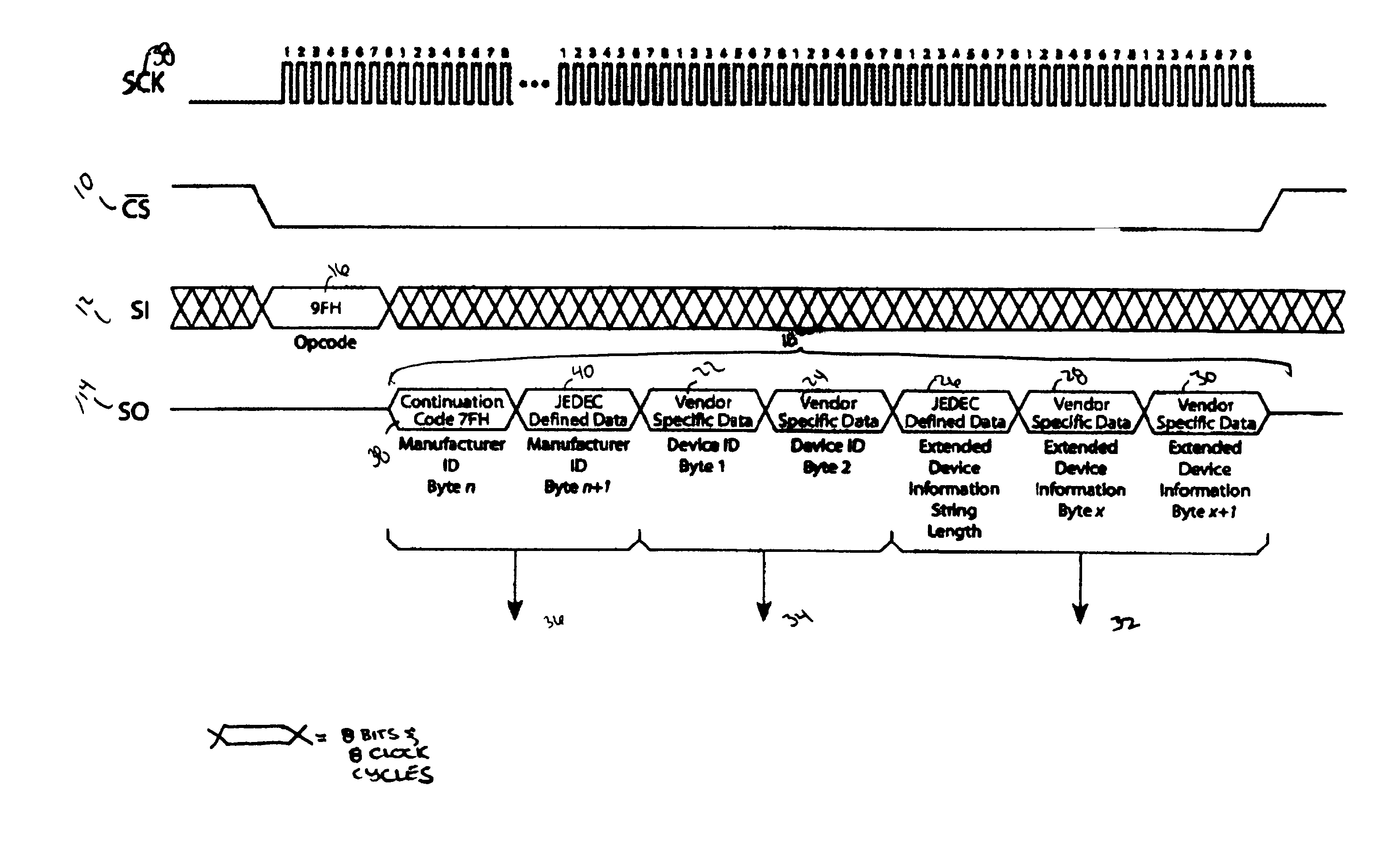
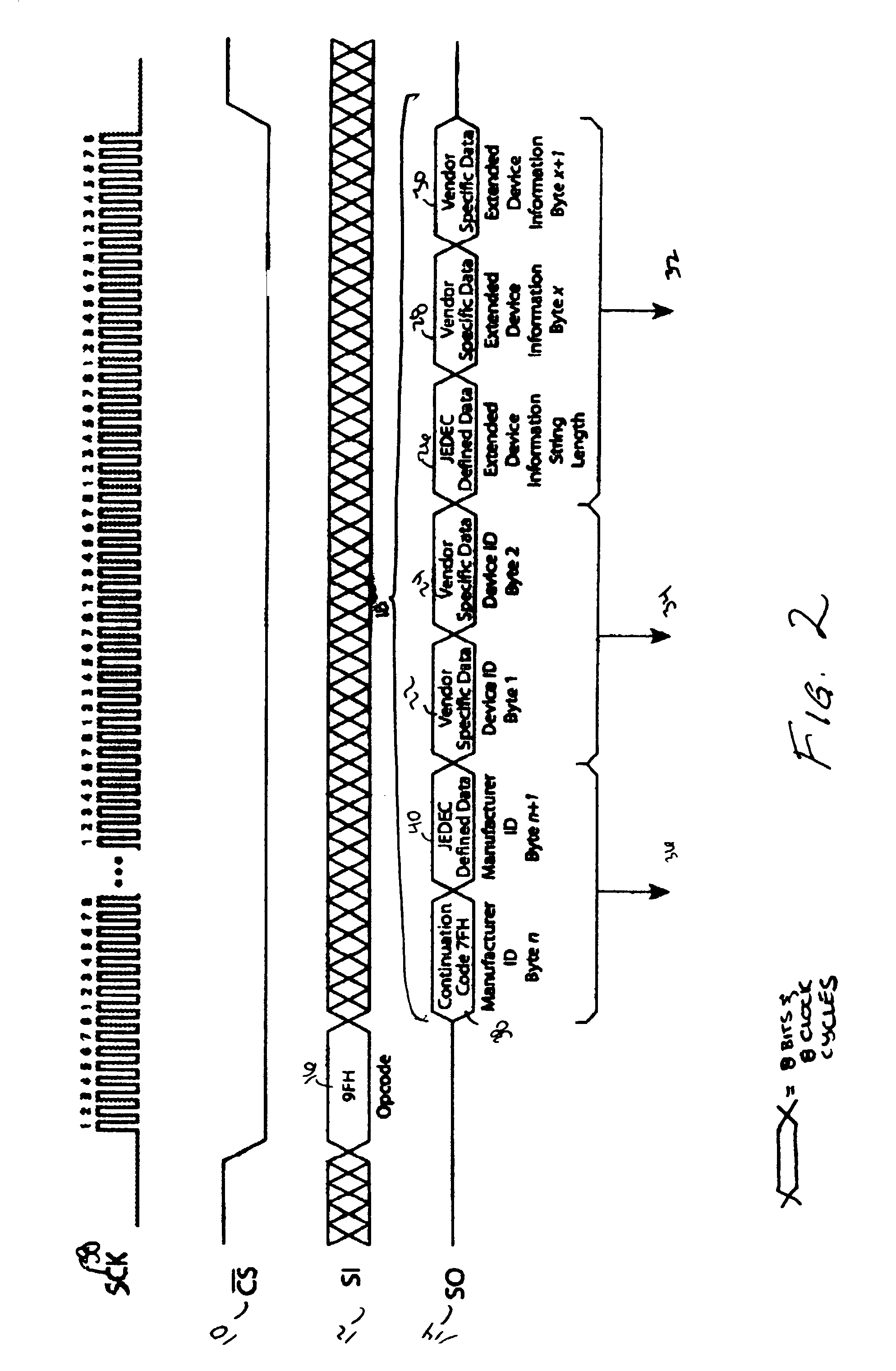
[0007]The present invention provides a command and reply serial communication method for obtaining information about an installed SPI memory device. A single command requesting information is sent to an SPI device which replies with a byte string of variable length including the manufacturer of the device, the device identification, and any extended device information, such as process technology, die revision, voltage levels, sector sizes, page sizes, erase times, etc. The reply indicates the JEDEC Manufacturer ID (based on JEDEC publication 106) and may include one or more continuation codes (in compliance with JEDEC publication 106) where the JEDEC Manufacturer ID cannot be indicated by one byte. The device is identified in two bytes in a vendor specific format indicating information such as device density, device family, and device version. In addition, the reply includes one byte which indicates the length of an extended device information string; this defines the relevant number of bytes which must be read to obtain additional information about the SPI device and prevents an associated microprocessor from reading unnecessary data.

Problems solved by technology

Despite the growing number of serial interface memory manufacturers (each of whom has been assigned a manufacturer identification by JEDEC publication 106, which standardized manufacturer identification codes encoded on devices), there is no common electronic method for identifying these serial interface memories, or SPI devices, on an SPI bus once these devices are installed.
This is problematic since different devices possess different characteristics, such as voltage range, erase times, etc. and may possess different architectures and command sets.
While there are common methods for identifying parallel non-volatile memory devices, such as those contained in the Common Flash Memory Interface (CFI) specification which uses a single, common command to identify different suppliers' devices, these methods cannot be employed in serial devices because serial devices lack the address and data lines which allow the random access of information in parallel devices.

Method used


Image

  • Method for identification of SPI compatible serial memory devices
  • Method for identification of SPI compatible serial memory devices
  • Method for identification of SPI compatible serial memory devices

Examples


Embodiment Construction

[0010]All devices discussed in the various embodiments of the invention are serial non-volatile (“NV”) memory devices compatible with the Serial Peripheral Interface (SPI) protocol and connected to an associated microprocessor. As shown in FIG. 1, a serial NV memory device has at least three lines: the chip select signal (CS) 10; serial in (SI) 12; and serial out (SO) 14. A clock signal (SCK) 38 is also shown. Each transition shown in FIGS. 1 and 2 represents 8 bits and 8 clock cycles.

[0011]Referring to FIG. 1, in order to identify a serial NV memory device, a microprocessor sends a command 16 in the form of encoded pulses in a data packet to the device requesting information to identify the device, its manufacturer, and provide any extended device information such as process technology, die revision, voltage levels, sector size, page size, erase times, etc. This command 16, in one embodiment an 8-bit opcode 1001 1111 (9FH), is clocked into the device. The opcode 16 must be dedicate...


PUM


Abstract

A method for identifying Serial Peripheral Interface (SPI) compatible serial interface memory devices. A microprocessor sends a single command requesting identification information to an SPI device installed on the SPI bus. A byte string, including the JEDEC manufacturer ID, device ID, and any extended device information, is sent back to the microprocessor. The byte string may include one or more continuation codes when the manufacturer ID exceeds 1 byte. The byte string also includes one byte indicating how many bytes of extended device information should be read by the microprocessor. The identification process, issuing the command and receiving the reply, is completed in one operation.

Description

FIELD OF THE INVENTION[0001]This invention relates to the identification of memory devices, particularly serial interface memory devices.BACKGROUND OF THE INVENTION[0002]Non-volatile memory devices are arranged in either a parallel interface arrangement or a serial interface arrangement. In past years, the parallel interface was more prevalent because of its fast, random access capability, making it ideal for direct code execution. In recent years, the serial interface has become more prevalent for storing personal preference and configuration data, offering a low pin count, low power consumption, and smaller packages. The parallel interface uses independent outputs and address pins with a rectangular array of memory devices. The serial interface typically uses a two wire configuration and sometimes a third wire for clock signals. Other wire arrangements can be found but a clock signal is always present.[0003]An example of a parallel interface is shown in U.S. Pat. No. 4,451,903 ent...

Claims


Application Information

Patent Timeline
IPC IPC(8): G06F3/00G11C7/10G11C7/20
CPCG11C7/10G11C7/20G11C2216/30G06F13/14G06F3/00
Inventor DECARO, RICHARD V.
Owner ARTEMIS ACQUISITION
Learn More