
Mobile terminal including first and second housings and an antenna

a mobile terminal and antenna technology, applied in the field of mobile terminals, can solve the problems of degrading the antenna gain of the antenna degrades under the effect of fingers, and the antenna gain of the aerial 401/b> is degraded, so as to prevent the degradation of the antenna gain

Inactive Publication Date: 2006-04-18
MITSUBISHI ELECTRIC CORP
View PDF37 Cites 26 Cited by
  • Summary
  • Abstract
  • Description
  • Claims
  • Application Information

AI Technical Summary

Benefits of technology

The present invention is a mobile terminal with a unique design that protects the antenna from degradation caused by contact with fingers and metal boards. The mobile terminal includes a first housing with a first antenna element, a second housing with a second antenna element, and a first pivotal mount between the first and second housings. The first antenna element is accommodated in the first housing, and the second antenna element is accommodated in the second housing. The second housing pivots towards or away from the other end of the first housing. This design prevents the first antenna element from contact with fingers and metal boards, and ensures stable antenna gain. The first antenna element can be a monopole, dipole, plate, inverted F, or loop antenna. The first housing has a first surface facing the user's head and the first antenna element is accommodated close to the first surface. The second housing has a second surface opposite the first surface and a conductive plate with constant potential is accommodated close to the second surface. The mobile terminal also includes a second antenna element at the other end of the second housing. The second housing is conductive and has an effect to shield electromagnetic wave, preventing degradation of antenna gain.

Problems solved by technology

In the above mentioned conventional mobile phone, however, the following problems are involved.
First, since the antenna is extending from the housing and exposed, it tends to contact with user's fingers.
In such a case, a problem arises that the antenna gain degrades under the effect of fingers.
As a result, the aerial is affected by the user's head, and thus the antenna gain tends to be degraded.
In addition, when the mobile phone is placed on a conductive material such as a metal board, a problem arises that antenna gain of the aerial 401 is degraded under the effect of the metal board, which in turn degrades speech quality.

Method used


Image

  • Mobile terminal including first and second housings and an antenna
  • Mobile terminal including first and second housings and an antenna
  • Mobile terminal including first and second housings and an antenna

Examples


first embodiment

[0046](First Embodiment)

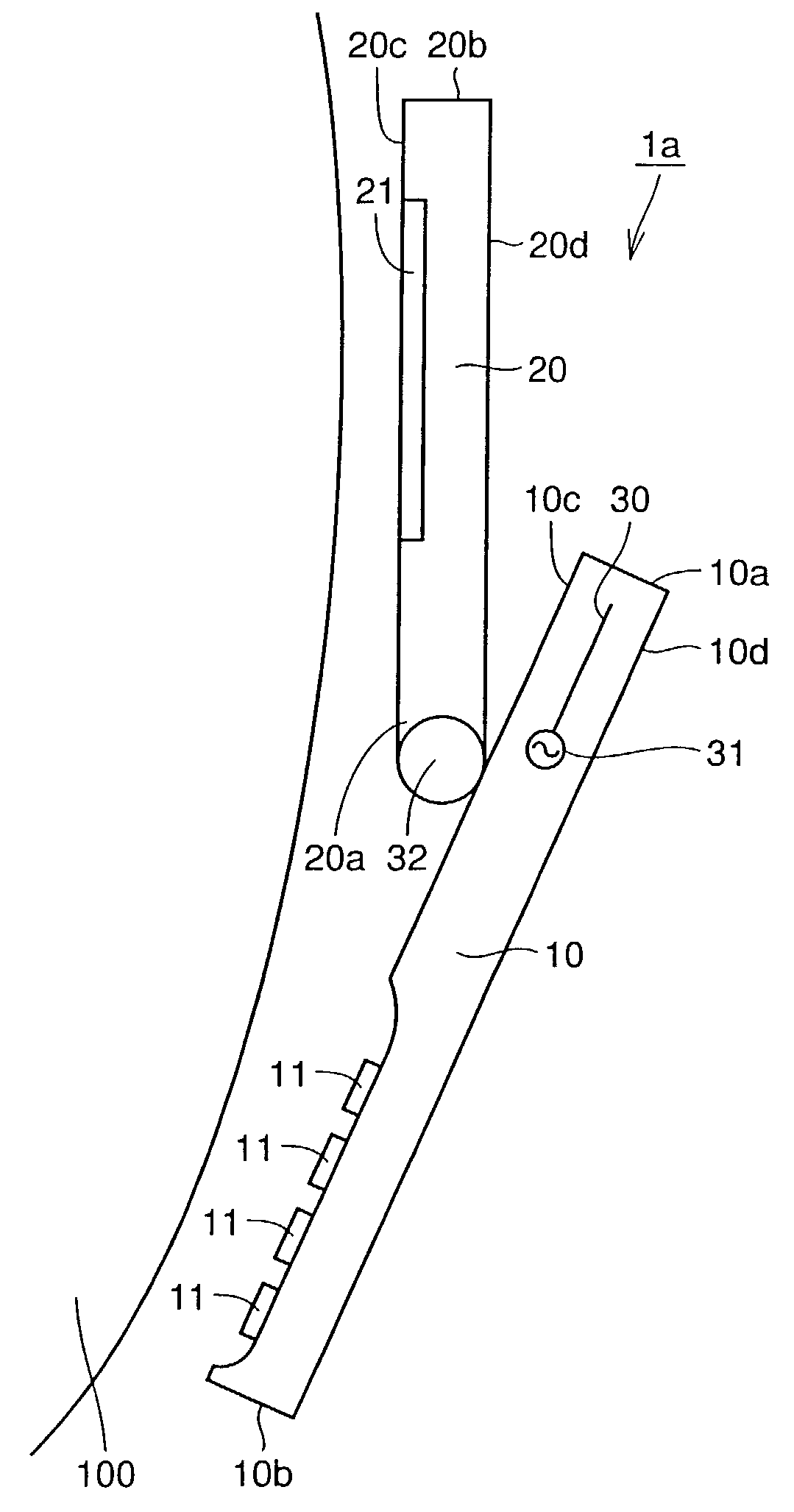
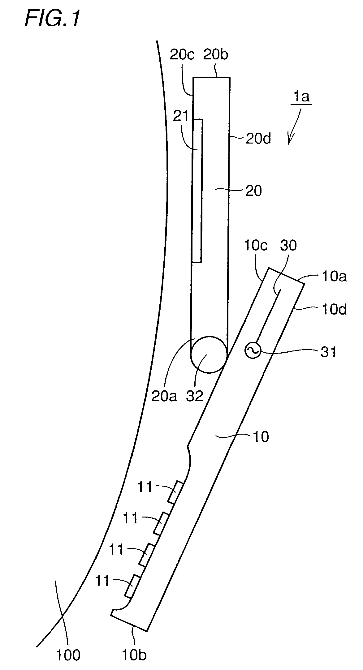
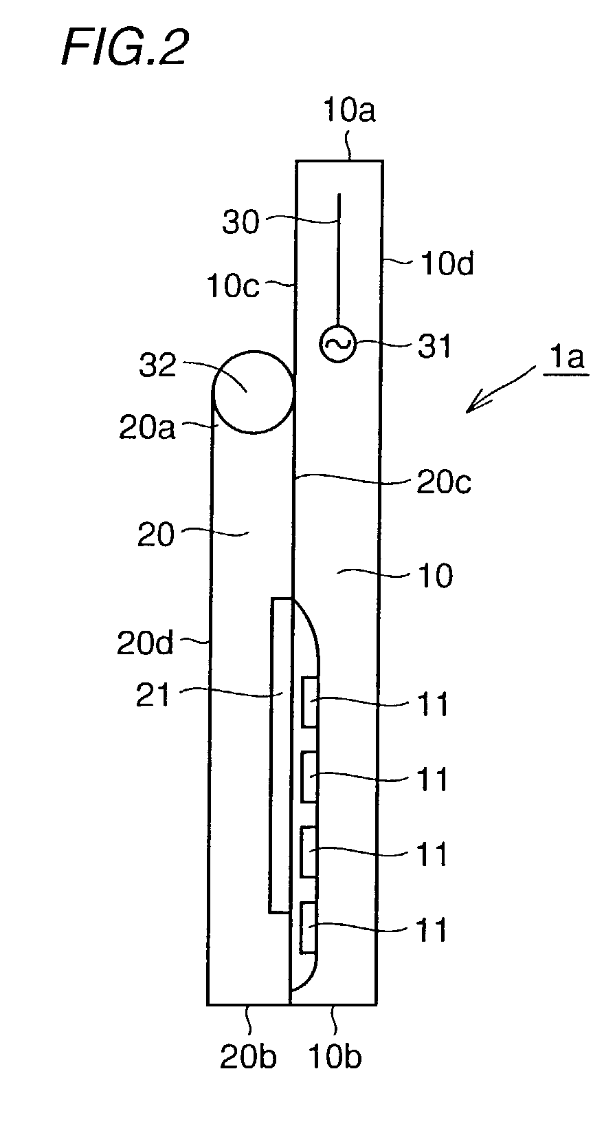
[0047]FIG. 1 is a side view of a mobile phone according to a first embodiment of the present invention. Referring to FIG. 1, the mobile phone la as a mobile terminal according to the present invention includes a lower housing 10 as a first housing having one end 10a and the other end 10b, an upper housing 20 as a second housing having one end 20a pivotally connected to the lower housing 10, and a monopole antenna 30 as a first antenna element accommodated close to one end 10a of the lower housing 10. The other end of the upper housing 20 pivots toward and away from the other end 10b of the lower housing 10. The mobile phone 1a is used in close proximity to a user's head with the other end 20b of the upper housing 20 being distanced from the other end 10b of the lower housing 10. Upon use, the lower housing 10 is disposed relative to the upper housing 20 so that the upper housing 20 intervenes between the monopole antenna 30 and the user's head 100.

[0048]The m...

second embodiment

[0056](Second Embodiment)

[0057]FIG. 3 is a schematic side view of a mobile phone according to a second embodiment of the present invention. Referring to FIG. 3, the mobile phone 1b according to the second embodiment of the present invention is different from the mobile phone 1a according to the first embodiment in that monopole antenna 30 is provided near the first surface 10c in the lower housing 10.

[0058]Thus structured mobile phone 1b primarily has the same effect as the mobile phone 1a according to the first embodiment. Further, since the monopole antenna 30 is disposed remotely from the second surface 10d of the lower housing 10 to which fingers may contact, degradation of antenna gain can further be alleviated. Additionally, with a thin type of lower housing 10, degradation of antenna gain due to the effect of fingers can be prevented as well.

third embodiment

[0059](Third Embodiment)

[0060]FIG. 4 is a schematic side view of a mobile phone according to a third embodiment of the present invention. Referring to FIG. 4, the mobile phone 1c according to the third embodiment of the present invention is different from the mobile phone 1a according to the first embodiment in that monopole antenna 30 is provided at one end 10a of the lower housing 10, i.e., at the top surface. The monopole antenna 30 extends approximately orthogonal to the direction to which the lower housing 10 extends.

[0061]Thus structured mobile phone 1c also has the same effect as the mobile phone 1a according to the first embodiment. Further, since the monopole antenna 30 is attached at the top surface of the lower housing 10, the attachment area of the antenna can be made smaller.


PUM


Abstract

A mobile phone includes a lower housing having one end and the other end, an upper housing having one end pivotally connected to the lower housing, and an antenna accommodated close to one end of the lower housing. The other end of the upper housing pivots toward and away from the other end of the lower housing. The mobile phone is used in close proximity to a user's head with the other end of the upper housing being distanced from the other end of the lower housing. Upon use, the lower housing is disposed relative to the upper housing so that the upper housing intervenes between the antenna and the user's head.

Description

TECHNICAL FIELD[0001]The present invention relates to a mobile terminal, and more specifically, to a mobile terminal as represented by a mobile phone.BACKGROUND ART[0002]The use of mobile phones has been spreading rapidly these days. Under such circumstances, the development regarding prevention of transmission gain degradation is proceeding. FIG. 27 is a perspective view of a conventional mobile phone. Referring to FIG. 27, a housing 402 of a mobile wireless radio as a mobile phone is divided into a first unit 402a having a receiver unit, and a second unit 402b without a receiver unit. The second unit 402b is foldably connected to the lower portion of the first unit 402a by a folding unit 402c. An aerial 401 as an antenna is formed to project upwardly toward the first unit 402a from an upper end surface 423 of the second unit 402b of the housing 402 of the mobile radio.[0003]In the above mentioned conventional mobile phone, however, the following problems are involved.[0004]First, ...

Claims


Application Information

Patent Timeline
Patent Type & Authority Patents(United States)
IPC IPC(8): H04M1/00H01Q1/08H01Q1/24H04B1/38H04M1/02
CPCH01Q1/084H01Q1/243H04B1/3838H01Q1/245H04M1/0214
Inventor SHOJI, HIDEAKIKATSURA, TAKATOSHIMATSUNAMI, YOSHINORIIMANISHI, YASUHITOTANAKA, TETSUYATAKETOMI, HIROKAZU
Owner MITSUBISHI ELECTRIC CORP
Learn More