
Mobile communication control method and system and mobile station thereof

a mobile communication control and control method technology, applied in transmission monitoring, power management, site diversity, etc., can solve the problems of degrading the reception signal quality of desired signal, disconnection of link, and increasing interference in downlink, so as to achieve the effect of increasing the transmission capacity

Inactive Publication Date: 2006-04-18
NEC CORP
View PDF12 Cites 17 Cited by
  • Summary
  • Abstract
  • Description
  • Claims
  • Application Information

AI Technical Summary

Benefits of technology

[0019]Accordingly, the present invention has been achieved to solve the above-mentioned problems, and it is an object of the invention to provide a mobile communication control method and system in which the trafic capacity is increased by suppressing the interference and the received signal quality is improved in such a manner that the base station is not selected and all of the handover base stations are enabled for transmission in the case where interference to other mobile stations is increased or the received signal quality of the link is degraded by selecting the base station.

Problems solved by technology

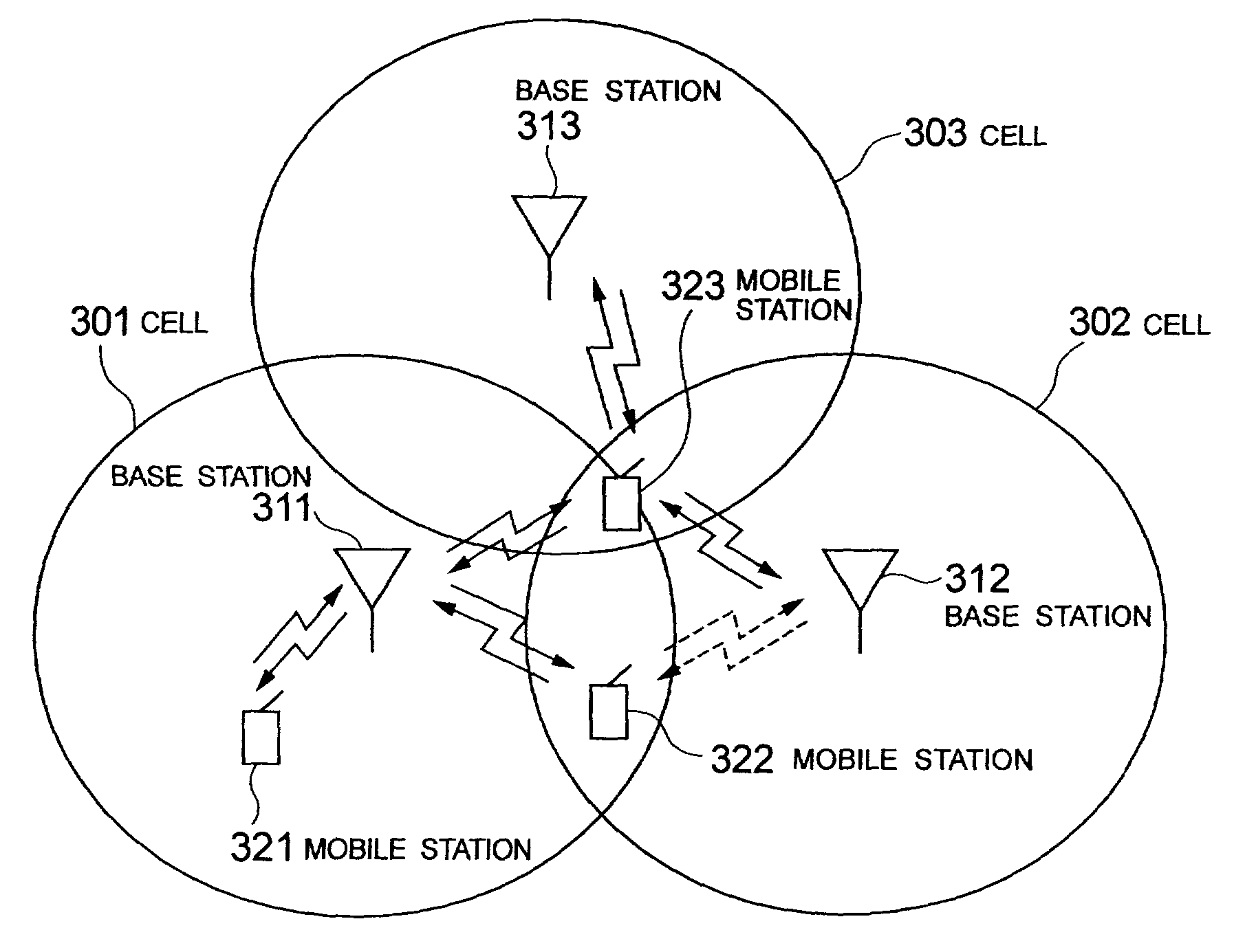
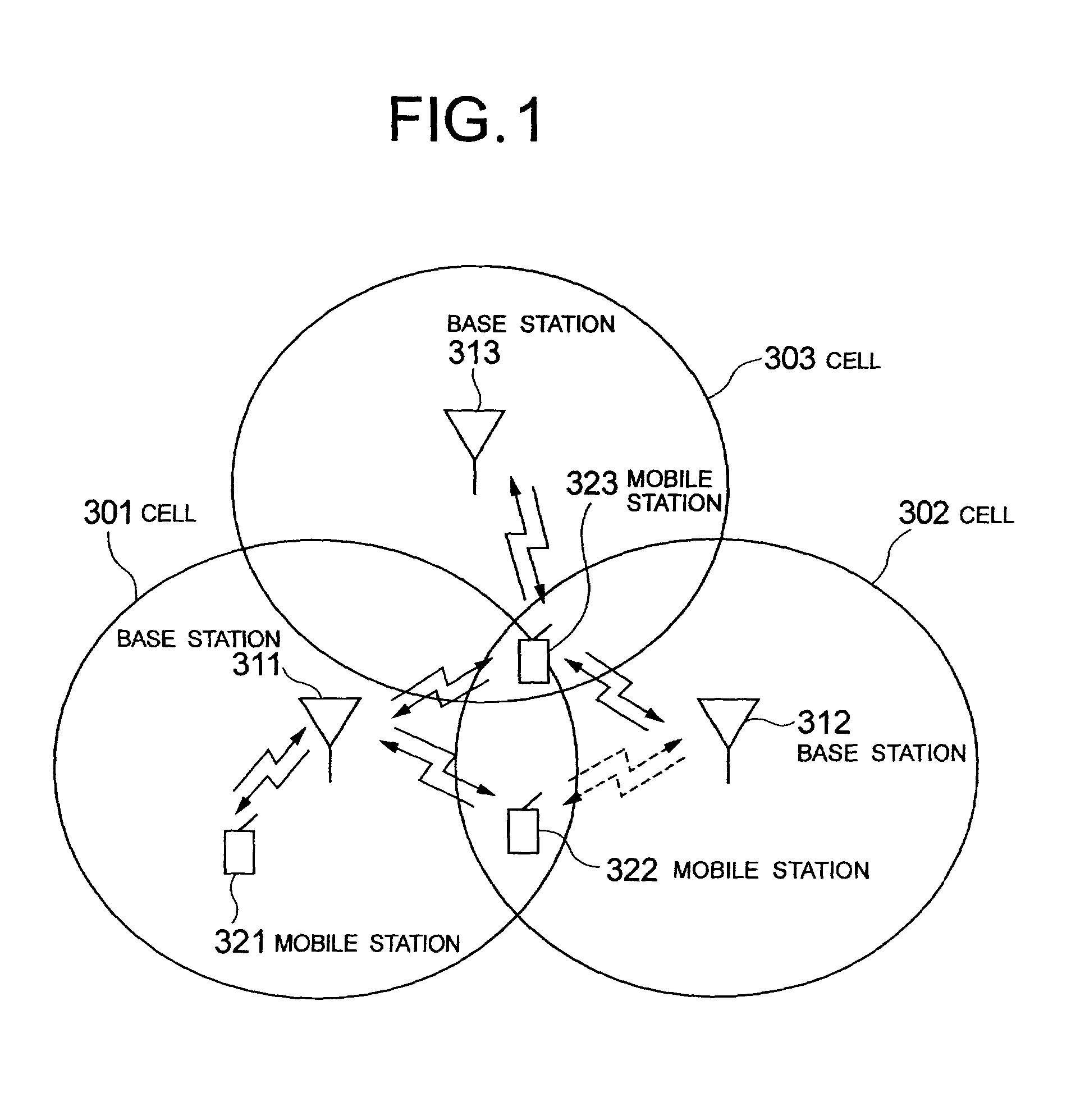
In a cellular system employing a direct sequence code division multiple access, since a same frequency band is used by a plurality of channels, transmission for other channels makes interference, in which if interference is increased, the received signal quality of desired signal is degraded, causing a disconnection of a link.
However, since in the soft handover a plurality of base stations are transmitted to one mobile station, there is a problem with the soft handover that interference increases in the downlink, and the trafic capacity decreases.
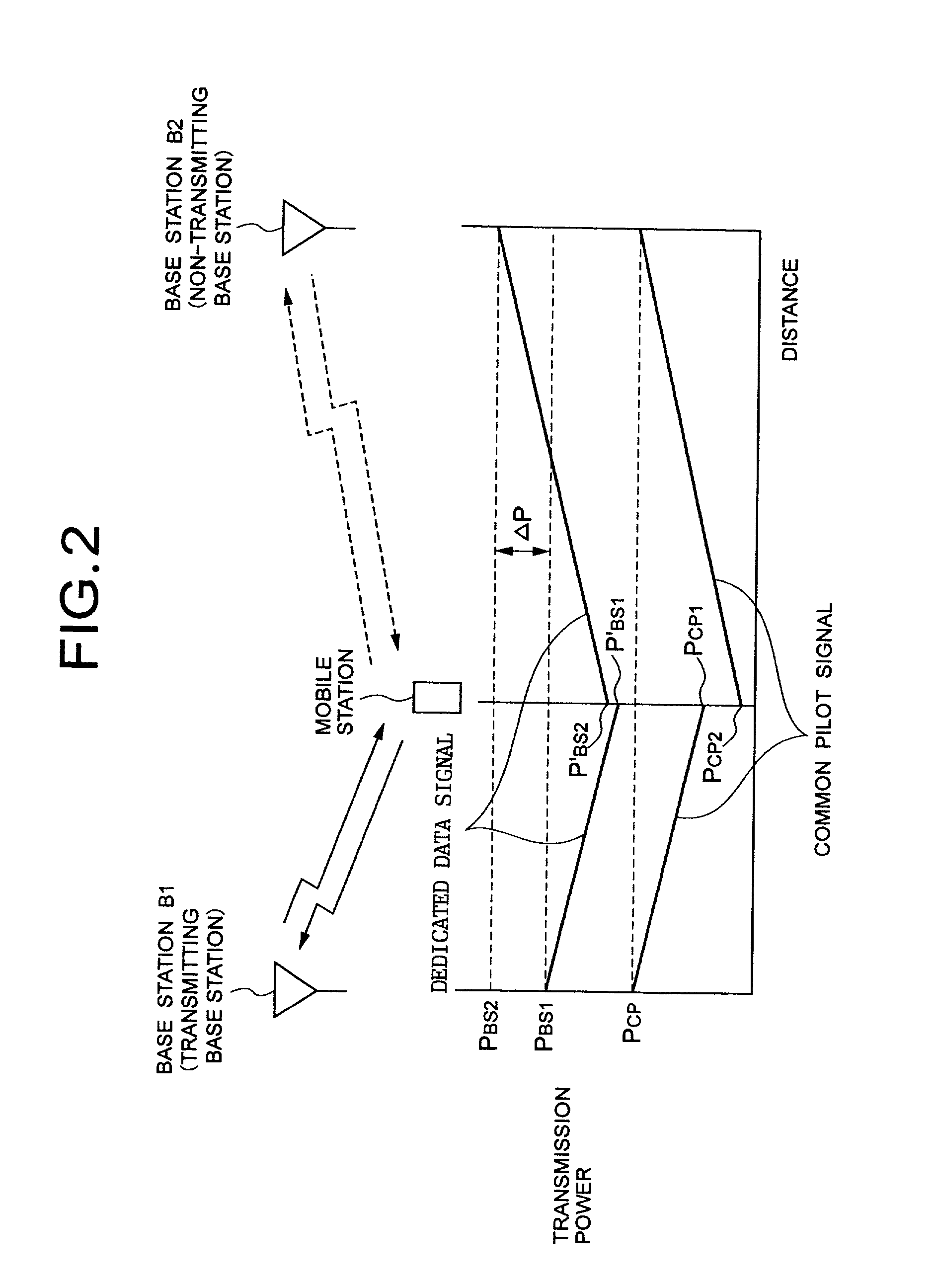
However, in the transmission power control of fast closed loop type, each handover base station receives a signal for instructing to increase or decrease the transmission power value from the mobile station and makes the independent control, whereby in some cases each handover base station has a different transmission power value due to a signal reception error.
Furthermore, the transmission power control of fast closed loop type, which is made so that the dedicated data signal at the mobile station has a predetermined received signal quality, has no effect on determining the signal for instructing to increase or decrease the transmission power value at the mobile station even in the case where the non-transmitting base station transmits the dedicated control signal at an excessive transmission power value, whereby the non-transmitting base station continues the transmission at the excessive transmission power value.
The transmission power control signal is received by each base station to control the transmission power value independently, whereby there is a difference in the transmission power value between handover base stations due to a reception error at the base station.
Hence, the base station BS2 produces a reception error during T1–T2, so that the total transmission power value of the dedicated data signal to the mobile station is not increased even if the transmission power value is higher.
Therefore, the interference on the other mobile stations increases and the trafic capacity decreases.
With the site selection diversity transmit power control, the number of base stations for transmission is smaller than in the normal soft handover, bringing about a problem that if there is a significant propagation loss, the received signal quality may be insufficient and degraded even if the transmission power value is increased to the maximum transmission power value of the base station.

Method used


Image

  • Mobile communication control method and system and mobile station thereof
  • Mobile communication control method and system and mobile station thereof
  • Mobile communication control method and system and mobile station thereof

Examples


first embodiment

[0049]FIG. 3 is a block diagram showing a configuration of the mobile station according to the invention. In FIG. 3, the mobile station comprises a receiving antenna 501 for receiving a radio signal transmitted from one or more base stations, a transmitting or receiving multiplexer (DUP) 502, a radio receiving portion (Rx) 503 for converting the radio signal into a receiving baseband signal, a received signal quality monitor 504 for measuring the received signal quality by receiving a common pilot signal, and a dedicated control signal from a plurality of base stations, a handover base station transmitted power difference estimating portion 505 for estimating a difference in transmission power value of the dedicated control signal between the handover base stations from the received signal quality of the common pilot signal and the dedicated control signal that is measured, a transmitting base station designating portion 506 for determining and designating the transmitting base stat...

second embodiment

[0059]FIG. 6 is a flowchart showing an operation at the mobile station according to the invention. A method of determining the transmitting base station at the mobile station that is performed at a predetermined interval will be described below.

[0060]First of all, the mobile station measures the received powers of common pilot signal and dedicated control signal transmitted from the transmitting base station (step 801). On the basis of the measured results, the transmission power value of dedicated data signal is estimated, and a transmission power value difference ΔP′ from the maximum transmission power value of the base station that is known beforehand is estimated (step 802). If this estimated power value is within a threshold value ΔP′th (step 803), all of the handover base stations are determined as the transmitting base station (step 804), or otherwise the transmitting base station is selected in accordance with the received signal quality of common pilot signal (step 805).

[00...

third embodiment

[0067]FIG. 8 is a flowchart showing the operation at the mobile station according to the present invention. A method of determining the transmitting base station at the mobile station that is performed at a predetermined interval will be described below.

[0068]First of all, the mobile station measures the received signal quality of dedicated data signal transmitted from the transmitting base station (step 1001). This measured result SIRmsr is compared with the minimum target value SIRmin of predetermined received signal quality (step 1002), in which if SIRmsrmin, all of the handover base stations are determined as the transmitting base station (step 1003), while if SIRmsr>SIRmin, the transmitting base station is selected in accordance with the received signal quality of common pilot signal (step 1004).

[0069]Thereafter, a signal indicating the determined transmitting base station is transmitted through an uplink, and notified to the handover base station (step 1005). The mobile statio...


PUM


Abstract

In case of making site selection diversity transmit power control, all handover base stations are enabled for transmission depending on a state of the transmission power value of a dedicated data signal from the base stations, thereby preventing a trafic capacity from decreasing due to an increase in the transmission power of a dedicated control signal at a non-transmitting base station, or a received signal quality from degrading at a mobile station because the transmission power value of the transmitting base station reaches a maximum transmission power of base station. A mobile station measures a common pilot signal and a dedicated control signal transmitted from each handover base station by means of a receiving monitor, estimates the transmission power value of the dedicated control signal at each handover base station from a difference thereof, and estimates a difference in the transmission power value of the dedicated control signal between the handover base stations. In the case where this difference is greater than or equal to a predetermined threshold value, a transmitting base station designating section designates all of the handover base stations to be enabled for transmission.

Description

BACKGROUND OF THE INVENTION[0001]1. Field of the Invention[0002]The present invention relates to a mobile communication control method and system and a mobile station, and more particularly to a system for determining a base station for transmission during hand-over in a cellular communication system.[0003]2. Description of the Prior Art[0004]In a cellular system employing a direct sequence code division multiple access, since a same frequency band is used by a plurality of channels, transmission for other channels makes interference, in which if interference is increased, the received signal quality of desired signal is degraded, causing a disconnection of a link. Accordingly, the trafic capacity, that is, the number of links capable of making communications while retaining a certain speech quality, depends on the amount of interference.[0005]Therefore, in a downlink of the cellular system employing the direct sequence code division multiple access, a transmission power value of th...

Claims


Application Information

Patent Timeline
Patent Type & Authority Patents(United States)
IPC IPC(8): H04Q7/20H04B7/005H04B7/26H04B7/02H04W52/40
CPCH04W52/40H04B7/022
Inventor TAKANO, NAHOKOHAMABE, KOJIRO
Owner NEC CORP
Learn More