Signal processing apparatus and method, program, and storage medium
a signal processing and signal processing technology, applied in the field of signal processing apparatus and method, a program, and a storage medium, can solve the problems of long conversion process and difficulty in implementing the discrete wavelet transformation of an imag
- Summary
- Abstract
- Description
- Claims
- Application Information
AI Technical Summary
Benefits of technology
Problems solved by technology
Method used
Image
Examples
first embodiment
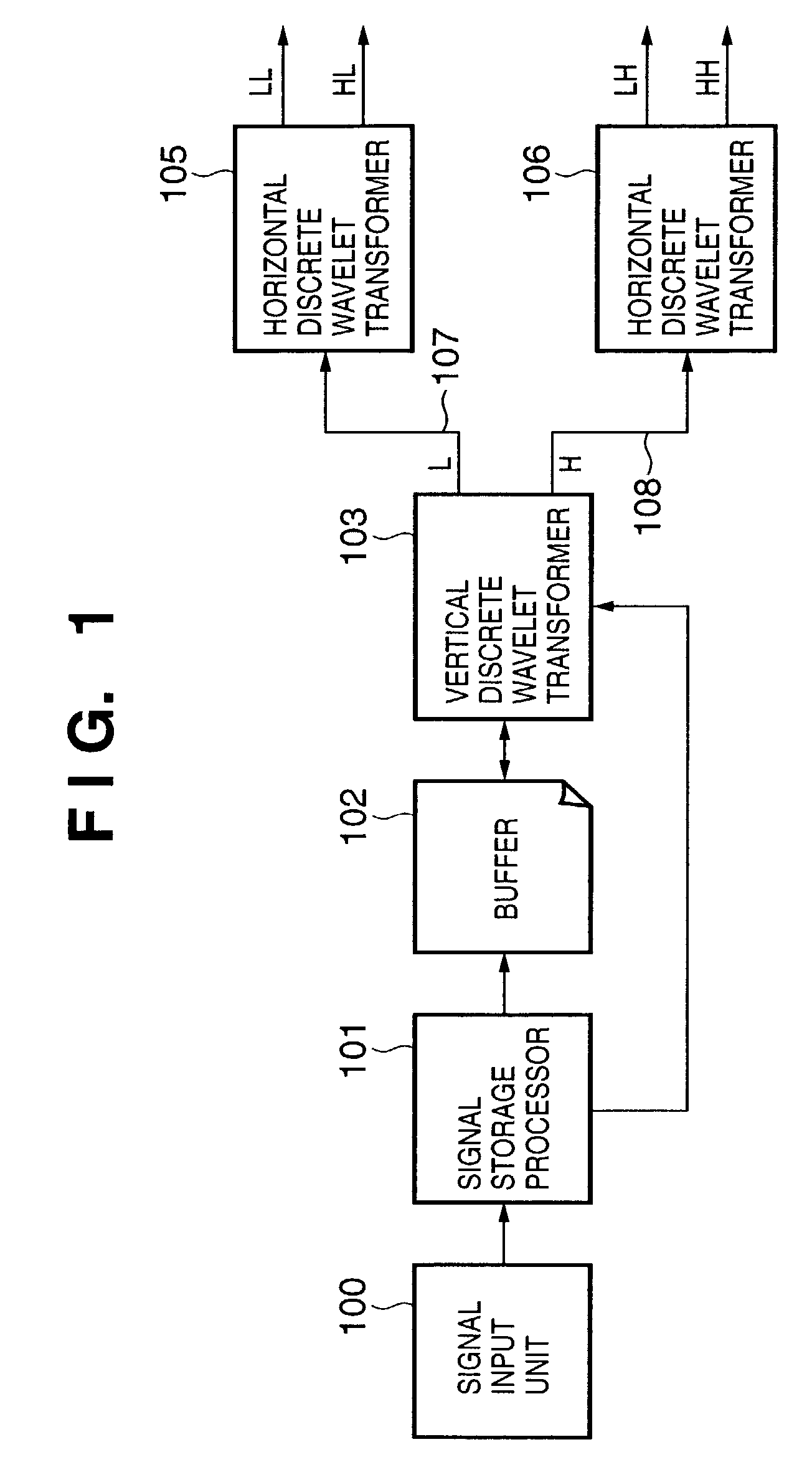
[0068]FIG. 1 is a block diagram showing the basic arrangement of a signal processing apparatus of this embodiment. Referring to FIG. 1, reference numeral 100 denotes a signal input unit; 101, a signal storage processor; 102, a buffer; 103, a vertical discrete wavelet transformer; 105 and 106, horizontal discrete wavelet transformers; and 107 and 108, signal lines.
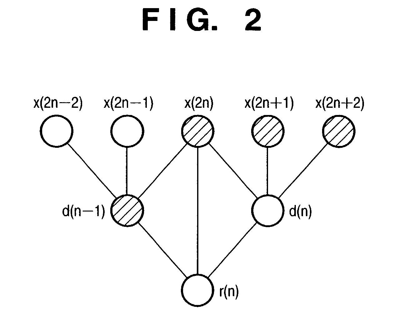
[0069]Assume that the signal processing apparatus of this embodiment computes the transforms of 2D signals which have X samples in the horizontal direction, and Y samples in the horizontal direction, and in which each sample is expressed by 8 bits, as in the conventional method described above. Also, Sx represents the number of samples in the horizontal direction of signals input to the apparatus of this embodiment. The buffer 102 stores signals and intermediate values of arithmetic operations for a plurality of lines, which are required to implement a 5×3 filter. As described above, upon implementation without lifting, sig...
second embodiment
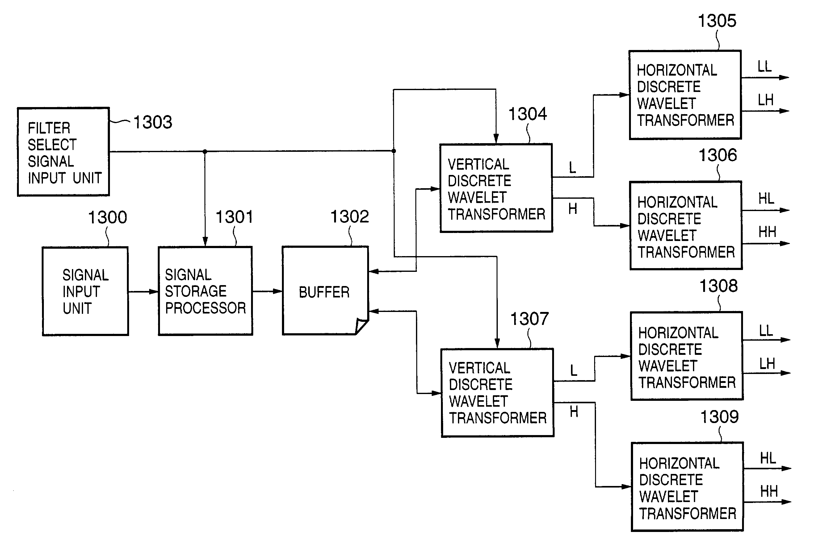
[0079]FIG. 7 is a block diagram showing the basic arrangement of a signal processing apparatus of this embodiment. Referring to FIG. 7, reference numeral 800 denotes a signal input unit; 801, a signal storage processor; 802, a buffer; 803, a vertical discrete wavelet transformer; 805 and 806, horizontal discrete wavelet transformers; and 807 and 808, signal lines. This block diagram is the same as the basic arrangement of the signal processing apparatus in the first embodiment (shown in FIG. 1), but processes executed by the respective units in the signal processing apparatus of this embodiment are different from those executed by the respective units in the signal processing apparatus of the first embodiment. The processes in the respective units in the signal processing apparatus of this embodiment will be explained below.
[0080]Assume that the signal processing apparatus of this embodiment computes the transforms of 2D signals which have X samples in the horizontal direction, and ...
third embodiment
[0092]FIG. 10 is a block diagram showing the basic arrangement of a signal processing apparatus of this embodiment. Referring to FIG. 10, reference numeral 800 denotes a signal input unit; 801, a signal storage processor; 1001, a vertical discrete wavelet transformer; 1002, a horizontal discrete wavelet transformer; and 1003 and 1004, signal lines. The same reference numerals in the third embodiment denote blocks which execute the same operations as in the second embodiment. The first and second embodiments comprise two horizontal discrete wavelet transformers, which respectively compute the discrete wavelet transforms of the coefficients of low- and high-frequency components output from the vertical discrete wavelet transformer in the horizontal direction. However, in the arrangement of this embodiment, only one horizontal discrete wavelet transformer is used.
[0093]The operation of the respective units of this embodiment will be described below using FIG. 10.
[0094]Assume that the s...
PUM
 Abstract
Description
Claims
Application Information
 - R&D
- Intellectual Property
- Life Sciences
- Materials
- Tech Scout
- Unparalleled Data Quality
- Higher Quality Content
- 60% Fewer Hallucinations
Browse by: Latest US Patents, China's latest patents, Technical Efficacy Thesaurus, Application Domain, Technology Topic, Popular Technical Reports.
© 2025 PatSnap. All rights reserved.Legal|Privacy policy|Modern Slavery Act Transparency Statement|Sitemap|About US| Contact US: help@patsnap.com


