
Systems and methods for rapidly automatically focusing a machine vision inspection system

a machine vision inspection and automatic focus technology, applied in the field of automatic focus systems, can solve the problems of auto focus speed limitations, machine vibration, distortion, etc., and achieve the effect of reducing the readout pixel set, fast and accurate automatic focus on a particular workpiece, and high precision and reliability

Active Publication Date: 2006-04-18
MITUTOYO CORP
View PDF5 Cites 152 Cited by
  • Summary
  • Abstract
  • Description
  • Claims
  • Application Information

AI Technical Summary

Benefits of technology

[0016]In contrast to each of the previously described known systems and methods for performing auto focus operations, the present invention provides high speed and high precision auto focusing suitable for a general purpose precision machine vision inspection system, while using relatively low-cost and flexible hardware. For example, relatively low-cost commercially available PC-compatible machine vision components and motion components may be used, along with conventional PC-based computer operating systems. Specialized motion elements such as piezoelectric actuators, or the like, and their associated control elements are not required in order to provide high precision in various exemplary embodiments of the systems and methods for rapidly automatically focusing an image capturing device according to this invention.
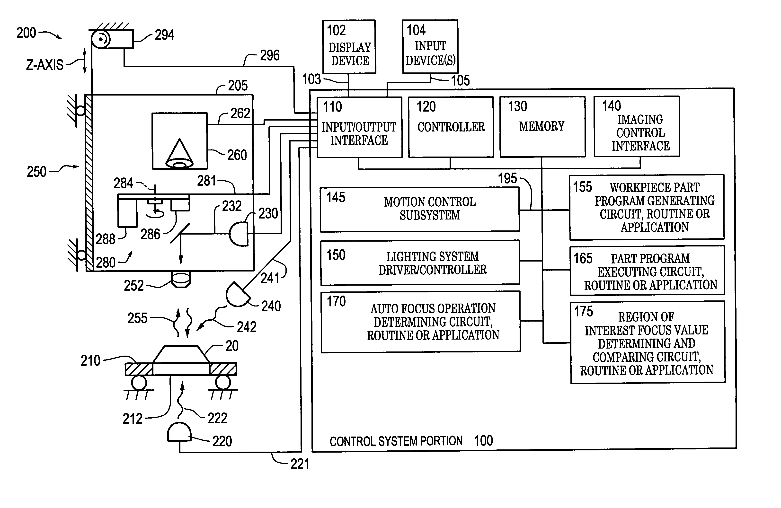
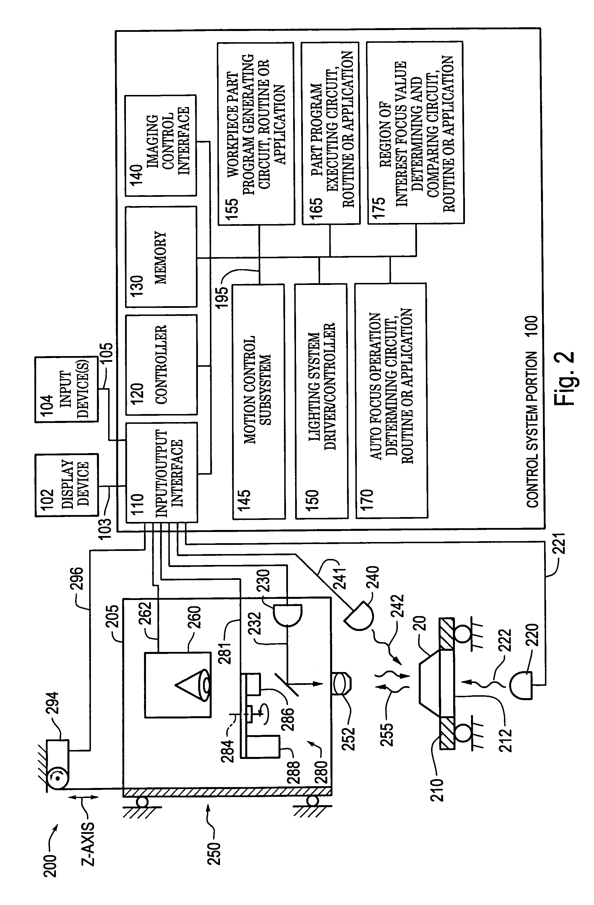
[0042]In various exemplary embodiments of the systems and methods according to this invention, one or more focus values are determined only for a limited region of interest captured in a reduced readout pixel set of various auto focus images. In various exemplary embodiments such focus values allow an estimated best focus position to be determined with high precision and at high speed using a computer or controller of the machine vision system.

Problems solved by technology

Another problem typical for related systems and methods is that machine vibrations, distortions and related auto focus position measurement errors occur when various vision machine elements are abruptly stopped just prior to an auto focus image acquisition.
The various previously described known systems and methods for performing auto focus operations suffer from either auto focusing speed limitations; auto focusing precision limitations; costly, specialized, and / or relatively inflexible hardware; and / or the lack of a suitable method for simply and reliably adapting and programming the auto focus operations for a variety of different workpieces or workpiece features, particularly when the auto focus operations include the use of strobed lighting.

Method used


Image

  • Systems and methods for rapidly automatically focusing a machine vision inspection system
  • Systems and methods for rapidly automatically focusing a machine vision inspection system
  • Systems and methods for rapidly automatically focusing a machine vision inspection system

Examples


Embodiment Construction

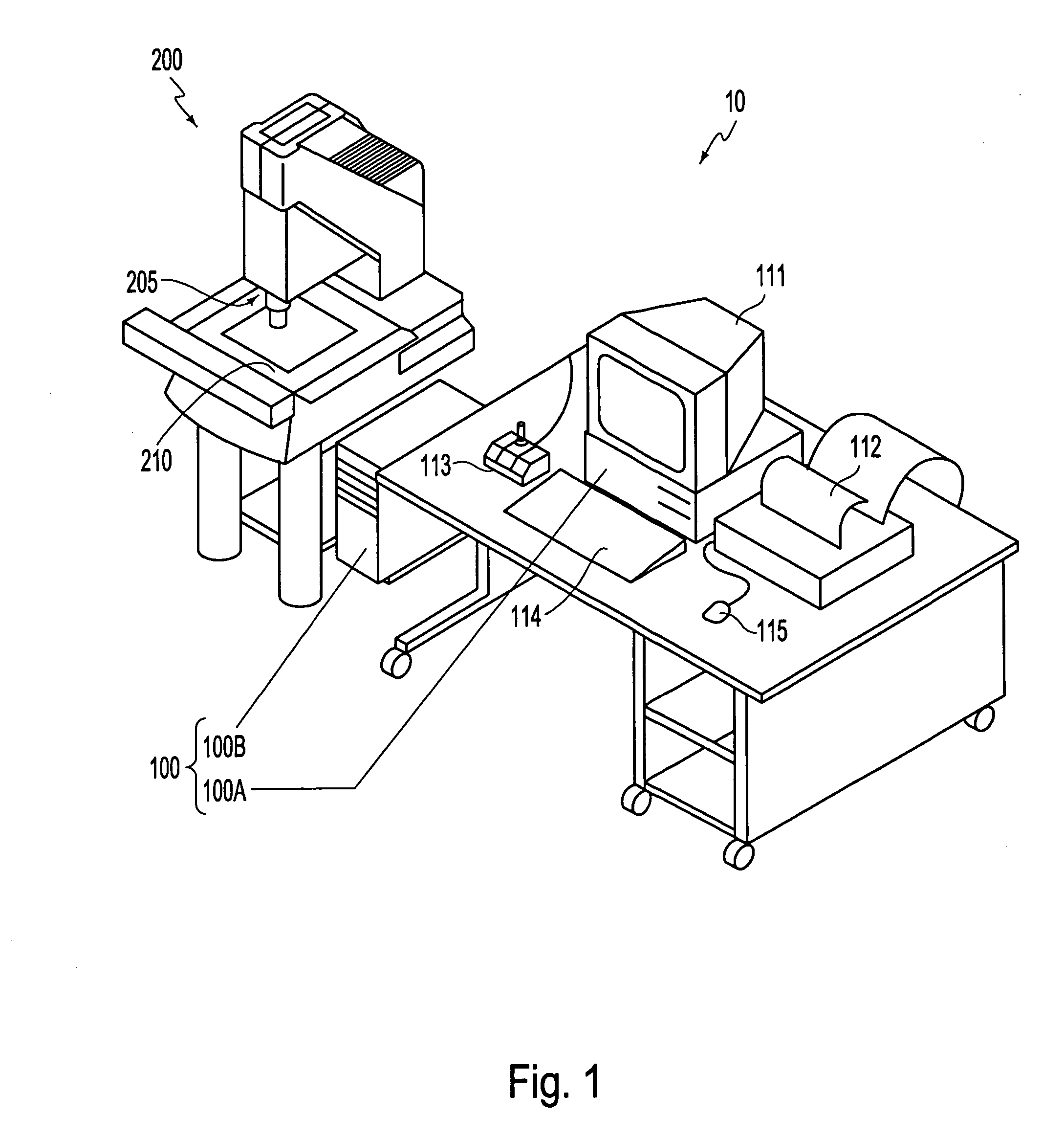
[0067]FIG. 1 is a block diagram of one exemplary embodiment of a general purpose programmable machine vision inspection system 10 in accordance with this invention. The machine vision inspection system 10 includes a vision measuring machine 200 that is operably connected to exchange data and control signals with a control system 100. The control system 100 is further operably connected to exchange data and control signals with one or more of a monitor 111, a printer 112, a joystick 113, a keyboard 114, and / or a mouse 115. The vision measuring machine 200 includes a moveable workpiece stage 210 and an optical imaging system 205 which may include a zoom lens or a number of interchangeable lenses. The zoom lens or interchangeable lenses generally provide various magnifications for the images provided by the optical imaging system 205.

[0068]The joystick 113 can typically be used to control the movement of the movable workpiece stage 210 in both the X and Y directions, which are generall...


PUM


Abstract

Auto focus systems and methods for a machine vision metrology and inspection system provide high speed and high precision auto focusing, while using relatively low-cost and flexible hardware. One aspect of various embodiments of the invention is that the portion of an image frame that is output by a camera is minimized for auto focus images, based on a reduced readout pixel set determined in conjunction with a desired region of interest. The reduced readout pixel set allows a maximized image acquisition rate, which in turn allows faster motion between auto focus image acquisition positions to achieve a desired auto focus precision at a corresponding auto focus execution speed that is approximately optimized in relation to a particular region of interest. In various embodiments, strobe illumination is used to further improve auto focus speed and accuracy. A method is provided for adapting and programming the various associated auto focus control parameters.

Description

BACKGROUND OF THE INVENTION[0001]This invention relates to systems and methods for automatically focusing a machine vision inspection system.[0002]2. Description of Related Art[0003]Methods for operating a machine vision inspection system with a camera and stage that are movable relative to one another to focus on and inspect selected features of a workpiece on the stage are generally known. Precision machine vision inspection systems can be used to obtain precise dimensional measurements of inspected objects and to inspect various other object characteristics. Such systems may include a computer, a camera and optical system and a precision stage that is movable in multiple directions to allow the camera to scan the features of a workpiece that is being inspected. One exemplary prior art system, of a type that can be characterized as a general-purpose “off-line” precision vision system, is the commercially available QUICK VISION™ series of vision inspection machines and QVPAK™ softw...

Claims


Application Information

Patent Timeline
Patent Type & Authority Patents(United States)
IPC IPC(8): G02B7/04G01B11/00G02B7/28G02B7/36G02B21/24G02B21/36G03B15/00H04N5/225H04N5/232
CPCG02B21/244H04N5/23212H04N5/2256G02B21/365H04N23/56H04N23/673
Inventor WASSERMAN, RICHARD M.GLADNICK, PAUL G.ATHERTON, KIM W.
Owner MITUTOYO CORP
Learn More