
Automatic ground marking method and apparatus

a marking method and automatic technology, applied in the direction of roads, construction, skiing, etc., can solve the problems of time-consuming and labor-intensive production and application of stencils for creating complex and large turf markings, distortion of logos, and inability to produce complex signs or logos on turf, etc., to achieve automatic and efficient marking level/even

Inactive Publication Date: 2006-04-18
EDGEROI
View PDF18 Cites 52 Cited by
  • Summary
  • Abstract
  • Description
  • Claims
  • Application Information

AI Technical Summary

Benefits of technology

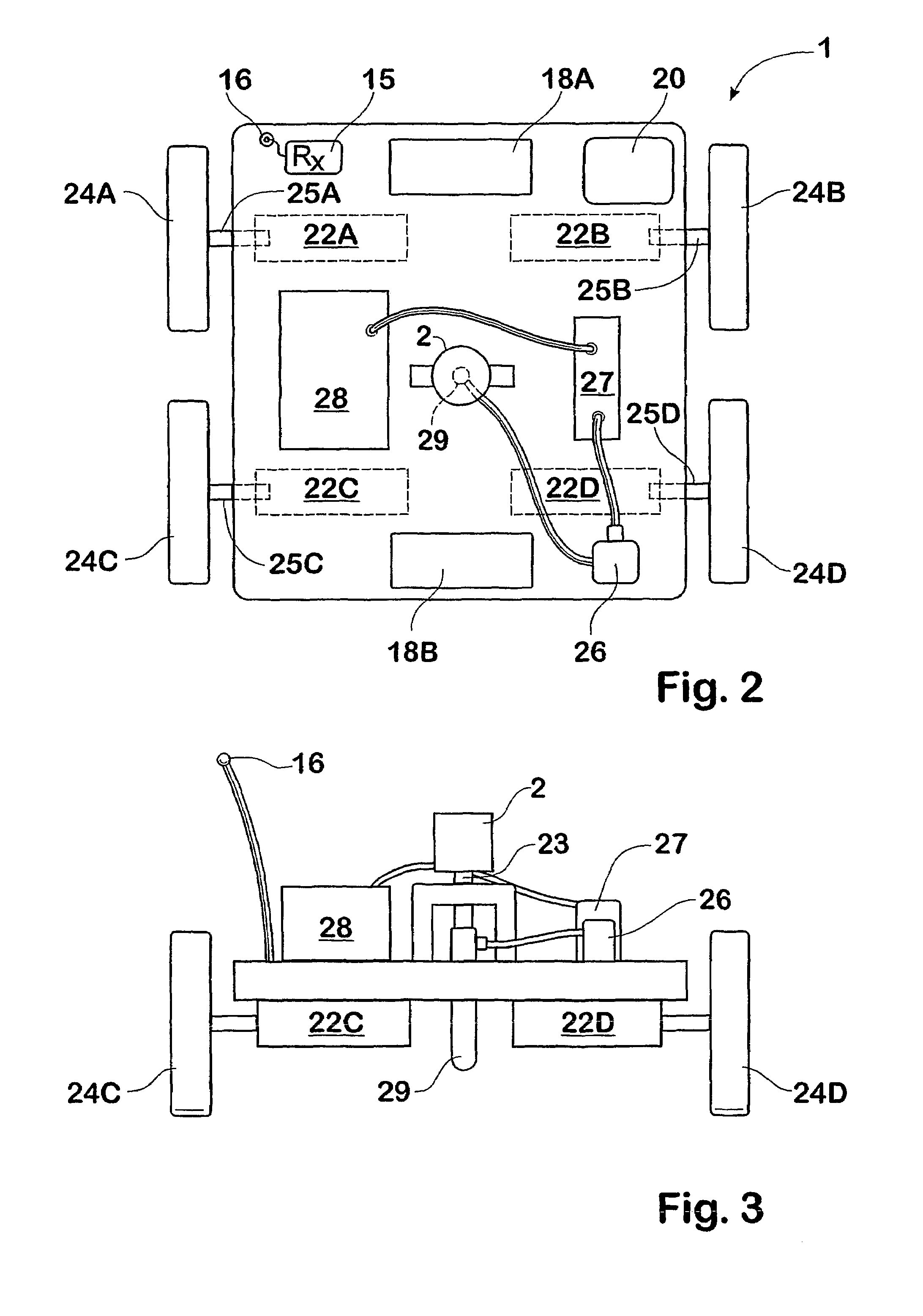
"The invention is an automatic ground marking apparatus that can be controlled by a user to mark out a predetermined sign on the ground. The apparatus includes a carriage with a controllable steering and drive system and a controllable marking system. The position of the carriage can be determined using a laser based electronic distance measuring system or a GPS receiver. The marking system includes a reservoir for a marking medium and a dispensing nozzle. The apparatus can be controlled using a computer software product that includes carriage position instructions, sign point instructions, and command instructions. The method of surveying an area involves initiating movement of the carriage over a predetermined path and monitoring its position using an EDM system. The technical effects of the invention include improved efficiency and accuracy in surveying and marking areas."

Problems solved by technology

Line marking machines are not suitable for producing complex signs or logos on turf.
The production and application of stencils for creating complex and large turf markings is time consuming and prone to error.
Large variations or undulations can cause distortion of logos and possibly affect viewing by spectators.
On a golf course there are deliberate variations and undulations in ground surfaces, which exacerbate problems with application and viewing of ground markings.

Method used


Image

  • Automatic ground marking method and apparatus
  • Automatic ground marking method and apparatus
  • Automatic ground marking method and apparatus

Examples


Embodiment Construction

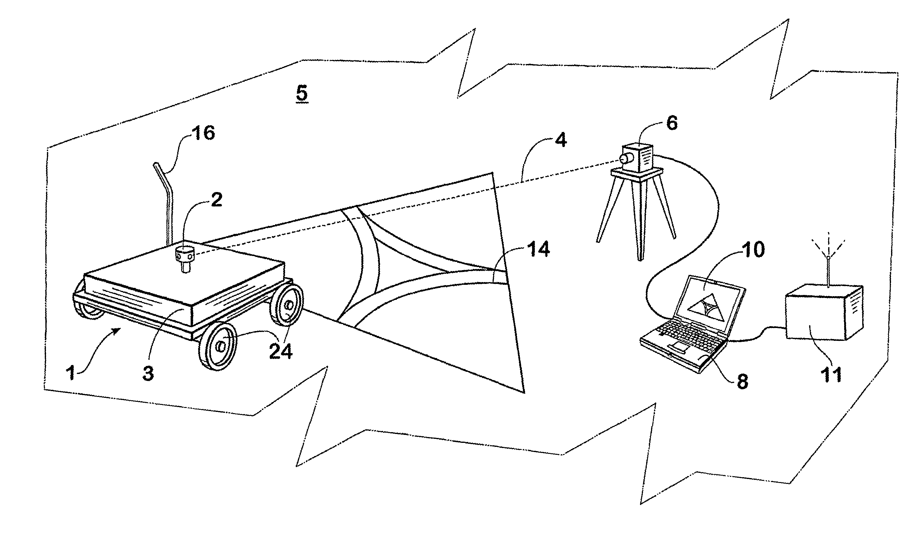
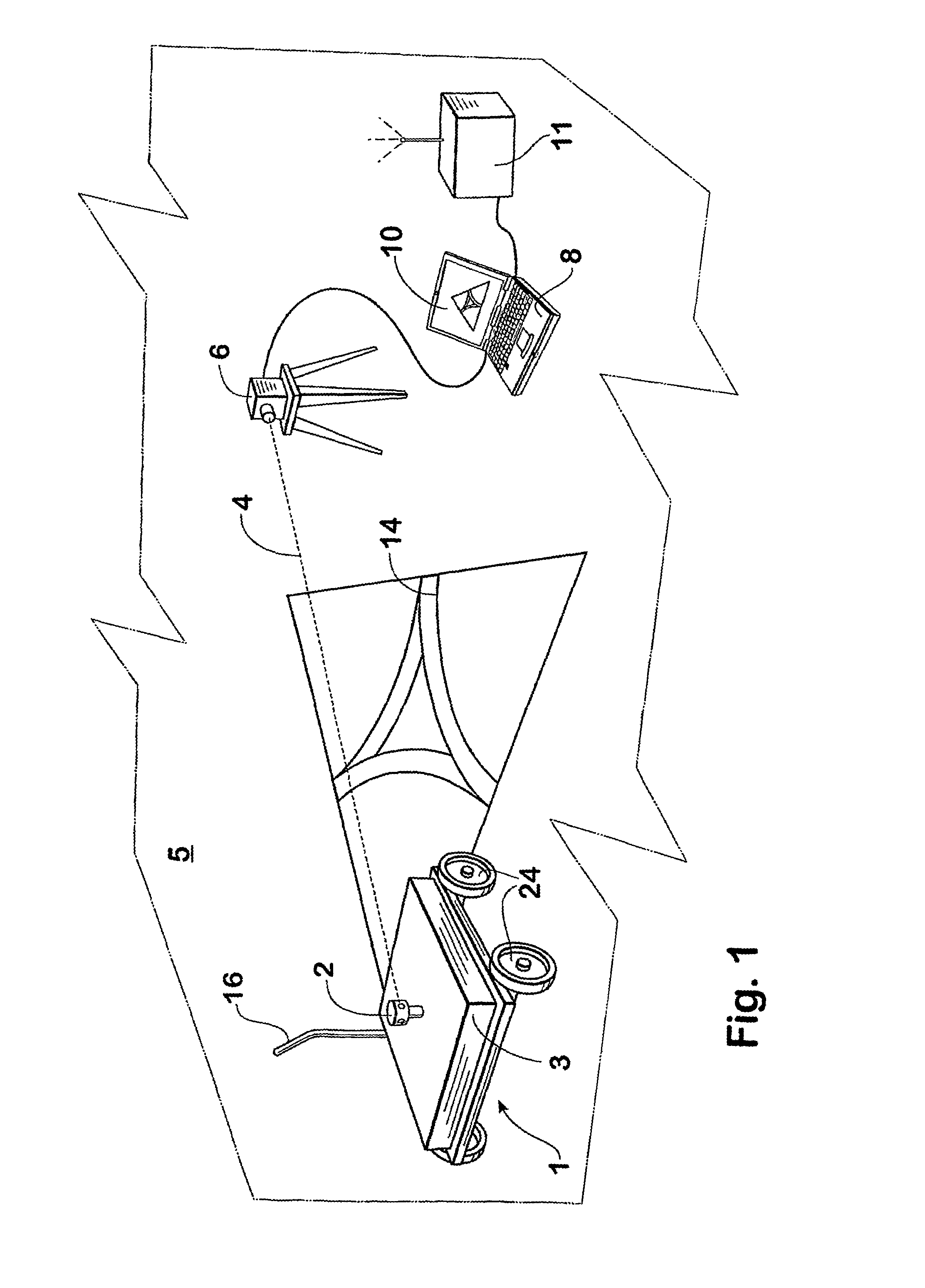
[0047]A preferred embodiment of an automatic turf marking system of the invention will be described in overview with reference to FIG. 1. A manoeuvrable paint dispensing carriage 1 for traversing the ground 5 includes a reflective tracking prism 2. A cover 3 covers the internal components of the carriage. An electronic distance measuring (EDM) base station 6 tracks the location of the carriage 1 by reflecting a laser beam 4 off the tracking prism. The base station 6 and prism 2 may be obtained as components of an AP-I1A auto-tracking electronic distance measuring system available from Topcon America Corporation of 37 West Century Road, Paramus, N.J. 07652, USA.

[0048]A lap-top computer 8 is coupled to a digital position data port on the base station 6. As will be explained, the computer 8 includes a processor that executes a software product that compares position data from the base station with a pre-stored data file. The data file contains coordinate points defining a desired sign ...


PUM


Abstract

An automatic ground marking apparatus including a carriage (1) responsive to carriage control signals for traversing the ground (5), the carriage having a controllable steering and drive system, a controllable marking system and a position determining system (6) arranged to determine the position of the carriage. The ground marking apparatus further includes a processor (8) responsive to the position determining system and operatively executing a software product for generating the carriage control signals to cause the carriage (1) to mark out a predetermined sign (14) on the ground. The position determining system (6) suitably employs a laser beam (4) and reflective tracking prism (2), and the predetermined sign may be defined by data points stored in a file (9) accessed by the processor (8) (FIG. 1).

Description

[0001]This application is a continuation of prior application No. PCT / AU02 / 00357, Mar. 25, 2002.BACKGROUND OF THE INVENTION[0002]1. Field of the Invention[0003]The present invention relates to an apparatus and method for making markings on ground surfaces such as turf playing fields and fairways. The invention has particular although not exclusive application where there is a need to automatically produce signs, such as logos or advertisements for example, on large ground surfaces whether even, sloped or undulating.[0004]2. Discussion of the Background Art[0005]A variety of arrangements for marking turf, such as the turf of playing fields, are known in the prior art. The simplest turf marking involves the application of straight lines to demarcate playing field boundaries. Commercially available line marking machines are used to facilitate such marking. Such machines may include a line of sight guide to aid the operator in producing a straight line between two reference points. Line...

Claims


Application Information

Patent Timeline
Patent Type & Authority Patents(United States)
IPC IPC(8): E01C23/07A63C19/06A63C19/08
CPCA63C19/08A63C19/06G05D1/0236G05D1/028
Inventor MAYFIELD, IANJOHNSON, MATTHEW J
Owner EDGEROI
Learn More