Method for operating optical sensors

Active Publication Date: 2006-04-18
SICK AG
View PDF10 Cites 1 Cited by
  • Summary
  • Abstract
  • Description
  • Claims
  • Application Information

AI Technical Summary

Benefits of technology

[0006]In view of the foregoing, it is an object of the present invention to provide an improved method for operating optical sensors, particularly code readers, and to provide a code reader which can be used in such a method. The present invention improves the error analysis by providing information about what caused the errors so they can be used to improve the rate with which errors can be detected.
[0009]Although picture compression as such is generally known, it provides significant advantages in the context of the present invention, particularly for detecting one- and two-dimensional codes, because the compressed pictures require only little memory space so that several pictures which led to error readings, so-called NOREAD-pictures, are readily stored. The presence of a series of NOREAD-pictures, for example 20 to 30, in the memory makes effective error analysis possible. This in turn improves the error recognition rate of the sensor, which makes it easier to correct errors. Thus, it is, for example, possible to adapt the algorithm for reading codes to codes which are difficult to read.
[0012]With picture compression, reference codes can be stored and compared with test codes for optimizing filters that are employed. In addition, picture data from the read codes can be transmitted better and more quickly to a processing unit via a bandwidth limited interface. This is particularly advantageous for long-distance analyses via computer networks.
[0020]In a refinement of the present invention, the degree or extent of compression is adjustable. This permits adapting the degree of compression to the encountered circumstances so that in each instance the highest possible, still acceptable degree of compression can be used, which ultimately saves memory space and speeds up data transmissions.
[0021]It is particularly advantageous when the degree of compression is automatically selected by the sensor, depending on certain parameters, such as the decodability of the compressed picture, the available storage media, or the bandwidth of the transmission channel, by having the sensor itself determine the acceptable degree of compression.

Problems solved by technology

However, what is stored is not the erroneous information, but the entire picture that was viewed by the sensor and led to the error reading.

Method used


Image

  • Method for operating optical sensors
  • Method for operating optical sensors
  • Method for operating optical sensors

Examples


Embodiment Construction

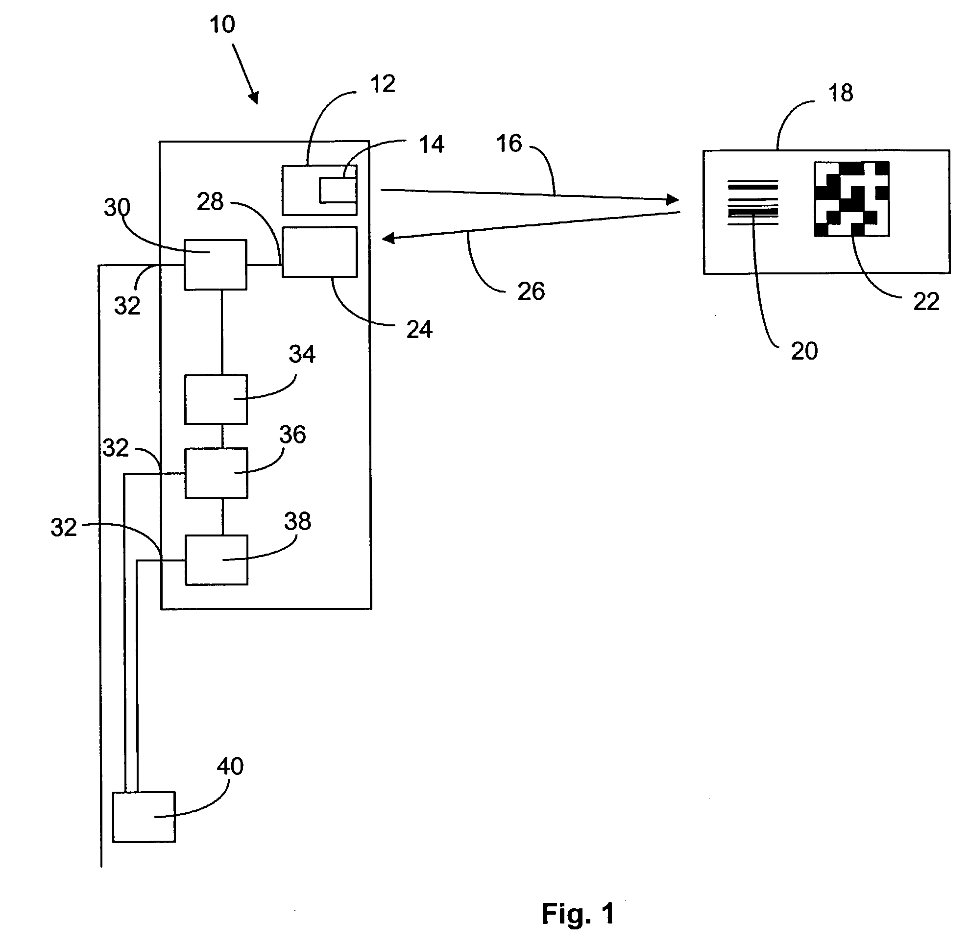
[0026]Referring to FIG. 1, a code reader 10 constructed in accordance with the present invention has a light emitter 12 with a light source 14 that emits a light beam 16. Light beam 16 illuminates an object 18 that carries a code 20 or 22. The code can be a one-dimensional bar code schematically illustrated at 20 or a two-dimensional code 22. Other codes, such as color codes, for example, can also be employed. To completely cover code 20 or 22 with light beam 16, code reader 10 has a light deflecting device (not separately shown) which scans the light beam over codes 20 or 22.

[0027]Light beam 16 can be linearly focused on object 18 so that, for one-dimensional codes 20, it illuminates the entire length of the code or, for two-dimensional code 20, so that the code is completely scanned by line-shaped light beam 16.

[0028]Code reader 10 further has a light receptor 24 which receives light 26 reflected by and / or returned from object 18. Light receptor 24 typically has its own optics. Li...


PUM


Abstract

A method for operating optical sensors, particularly code readers, which have a light receptor that receives light reflected and / or returned from an object. A picture is generated from the received light and the content of the picture, such as a code, is read. At least some pictures are compressed with a picture compression algorithm of the sensor. To improve the operation of such optical sensors, especially code readers, and to improve the analysis of error detection from knowing the causes for errors, only pictures which have error information are compressed and stored. The code reader is constructed to perform these functions.

Description

BACKGROUND OF THE INVENTION[0001]The present invention relates to optical sensors, and especially to optical code readers, and to a method for operating such sensors, which involves receiving reflected light with a light receptor, generating a picture therewith, reading the picture (code) and compressing at least some of the pictures with a picture compression algorithm.[0002]Code readers read codes, such as one-dimensional bar codes or two-dimensional matrix codes, and they operate according to a variety of principles. Code readers which employ the scanner principle read the code by scanning a light beam over the object in question, for example a label carrying a bar code. Light reflected or returned by the object is received by a light receptor and converted into electronic signals. Bar code information is derived from amplitude information of the electric signals.[0003]Two-dimensional codes are typically read with code readers that operate on the camera principle. The object in q...

Claims


Application Information

Patent Timeline
IPC IPC(8): G02B26/08G06K7/10
CPCG06K7/10722
Inventor REICHENBACH, JUERGENHAFNER, CARL JOSEPHHAUSER, PETERFILLHARDT, CHRISTIANE
Owner SICK AG
Why Eureka
Try Eureka