High frequency switch and high frequency radio communication apparatus
a high frequency radio and switch technology, applied in the direction of electrical equipment, transmission, etc., can solve the problems of a larger circuit size, complexity will increase,
- Summary
- Abstract
- Description
- Claims
- Application Information
AI Technical Summary
Benefits of technology
Problems solved by technology
Method used
Image


Examples
embodiment 1
[0096]First, mainly referring to FIG. 1, the configuration of a high frequency switch will be discussed according to Embodiment 1. FIG. 1 is a block diagram showing the high frequency switch of Embodiment 1.
[0097]A high frequency switch 10 of Embodiment 1 is a high frequency switch for four bands that has a filtering function permitting passage of transmissions frequency band and reception frequency bands included in an EGSM frequency band serving as an example of a first frequency band of the present invention, an AMPS frequency band serving as an example of a second frequency band of the present invention, a DCS frequency band serving as an example of a third frequency band of the present invention, and a PCS frequency band serving as an example of a fourth frequency band of the present invention. The high frequency switch 10 comprises a first switched circuit 1 serving as an example of first transmission reception changeover means of the present invention, a second switched circu...
embodiment 2
(Embodiment 2)
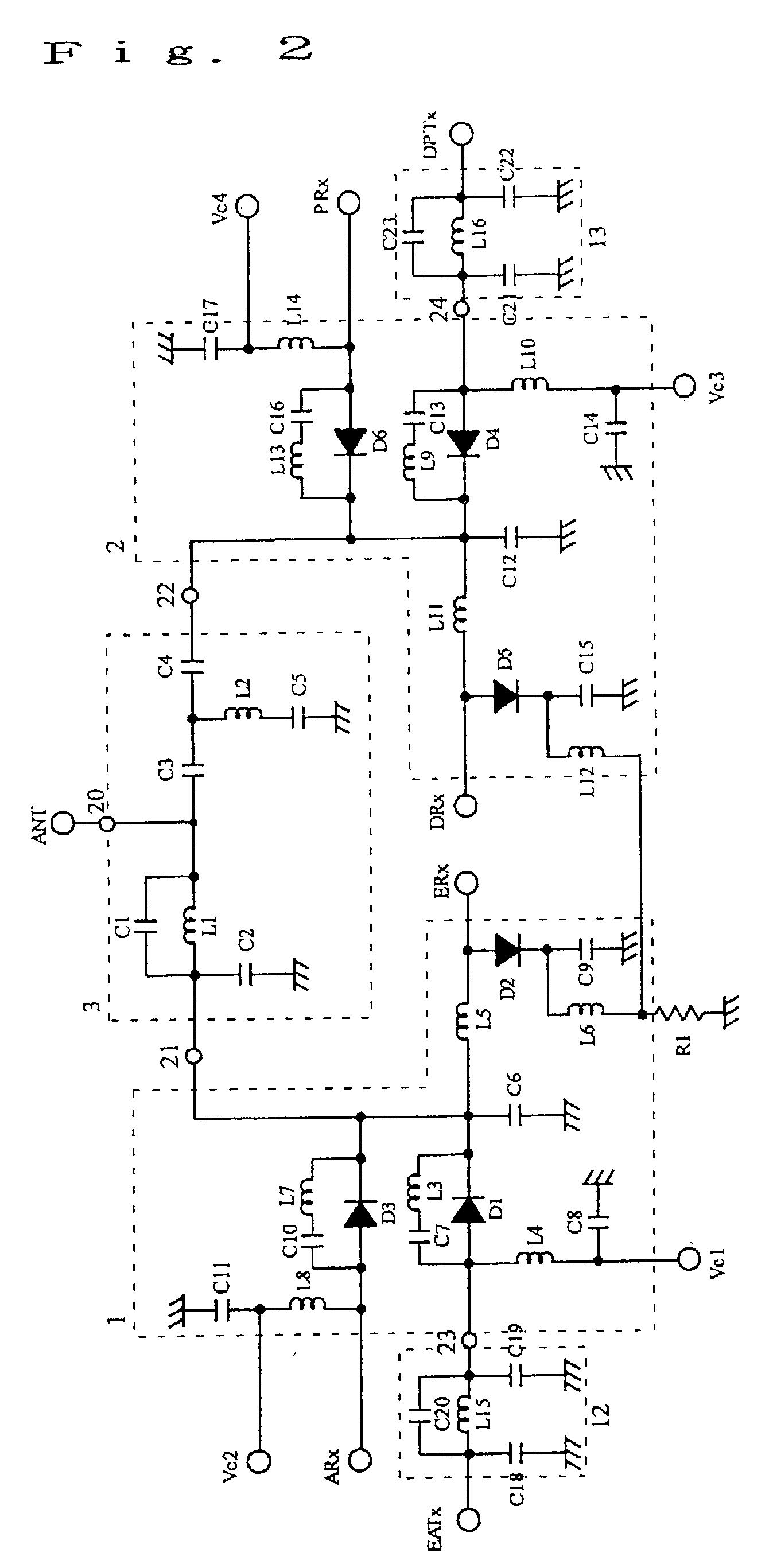
[0127]Next, referring to FIG. 3, the following will discuss the configuration of a high frequency switch according to Embodiment 2. FIG. 3 is a block diagram showing the high frequency switch of Embodiment 2.
[0128]As in the case of the high frequency switch of Embodiment 1, a high frequency switch 30 of Embodiment 2 is a high frequency switch for four bands that has a filtering function permitting transmission on transmission frequency bands and reception on reception frequency bands included in a first frequency band (EGSM), a second frequency band (AMPS), a third frequency band (DCS), and a fourth frequency band (PCS). The high frequency switch 30 comprises first and second switched circuits (transmission reception changeover circuit) 1 and 2 and a branching filter circuit 3. Thus, the following will discuss parts different from those of the high frequency switch 10 of Embodiment 1.
[0129]In the high frequency switch 30 of Embodiment 2, a control power terminal which ...
embodiment 3
(Embodiment 3)
[0150]Referring to FIGS. 5 and 6, the following will discuss the configuration of a high frequency switch according to Embodiment 3. FIG. 5(a) is an explanatory drawing showing the high frequency switch (front) according to Embodiment 3. FIG. 5(b) is an explanatory drawing showing the high frequency switch (back) according to Embodiment 3. FIG. 6 is a partial exploded perspective view showing the high frequency switch according to Embodiment 3.
[0151]The high frequency switch of Embodiment 3 is constituted by a plurality of laminated dielectric layers DL. The number of stacked dielectric layers is properly selected according to necessary characteristics of the high frequency switch.
[0152]Besides, as the dielectric layer, a so-called glass ceramic substrate is applicable, in which low-melting glass frit is mixed with ceramic powder such as a compound having forsterite or alumina as a main component. Further, on green sheets formed by slurry obtained by mixing an organic ...
PUM
 Abstract
Description
Claims
Application Information
 - R&D
- Intellectual Property
- Life Sciences
- Materials
- Tech Scout
- Unparalleled Data Quality
- Higher Quality Content
- 60% Fewer Hallucinations
Browse by: Latest US Patents, China's latest patents, Technical Efficacy Thesaurus, Application Domain, Technology Topic, Popular Technical Reports.
© 2025 PatSnap. All rights reserved.Legal|Privacy policy|Modern Slavery Act Transparency Statement|Sitemap|About US| Contact US: help@patsnap.com