Receiving device used in high-definition television

a technology of receiving device and high-definition television, which is applied in the direction of color television details, selective content distribution, television system, etc., can solve the problems of increasing the cost of the device, signal cannot be received, so as to achieve accurate demodulation of received signals and simple configuration

Inactive Publication Date: 2006-04-11
FUNAI ELECTRIC CO LTD
View PDF10 Cites 1 Cited by
  • Summary
  • Abstract
  • Description
  • Claims
  • Application Information

AI Technical Summary

Benefits of technology

[0009]It is an object of the invention to provide a receiving device for use in high-definition television that can demodulate a received signal accurately in a simple configuration.
[0014]Also, a frequency-deviation measuring section measures a deviation of the carrier wave frequency for each channel and stores a measurement result in the memory. The control unit controls the frequency of a signal output from the oscillator based on the frequency deviation stored in the memory. Therefore, even if the frequency of a carrier wave is shifted on the side of a broadcasting station, a signal of an appropriate frequency can be output from the oscillator to the frequency-shifted carrier wave. It is, therefore, possible to demodulate a received signal securely free of such a problem that no pilot signal is present in an IF signal within a predetermined band width filtered by the filter or that the pilot signal, even if present, cannot be extracted.

Problems solved by technology

However, if the frequency accuracy of the output signal of the oscillator equipped in the receiving device is poor, the frequency of the IF signal output from the tuner is shifted from an appropriate value.
If this frequency error is large, no pilot signal is present in the IF signal within the predetermined band width filtered by the SAW filter or that the pilot signal, even if present, cannot be extracted.
This accident leads to such a problem that the signal cannot be received.
This accident, therefore, leads to a problem that the signal cannot be received like in the case mentioned above where the frequency error is large.
The configuration thereof, however, is complicated, to increase the costs of the device, so it is not a practical method.

Method used


Image

  • Receiving device used in high-definition television
  • Receiving device used in high-definition television
  • Receiving device used in high-definition television

Examples


Embodiment Construction

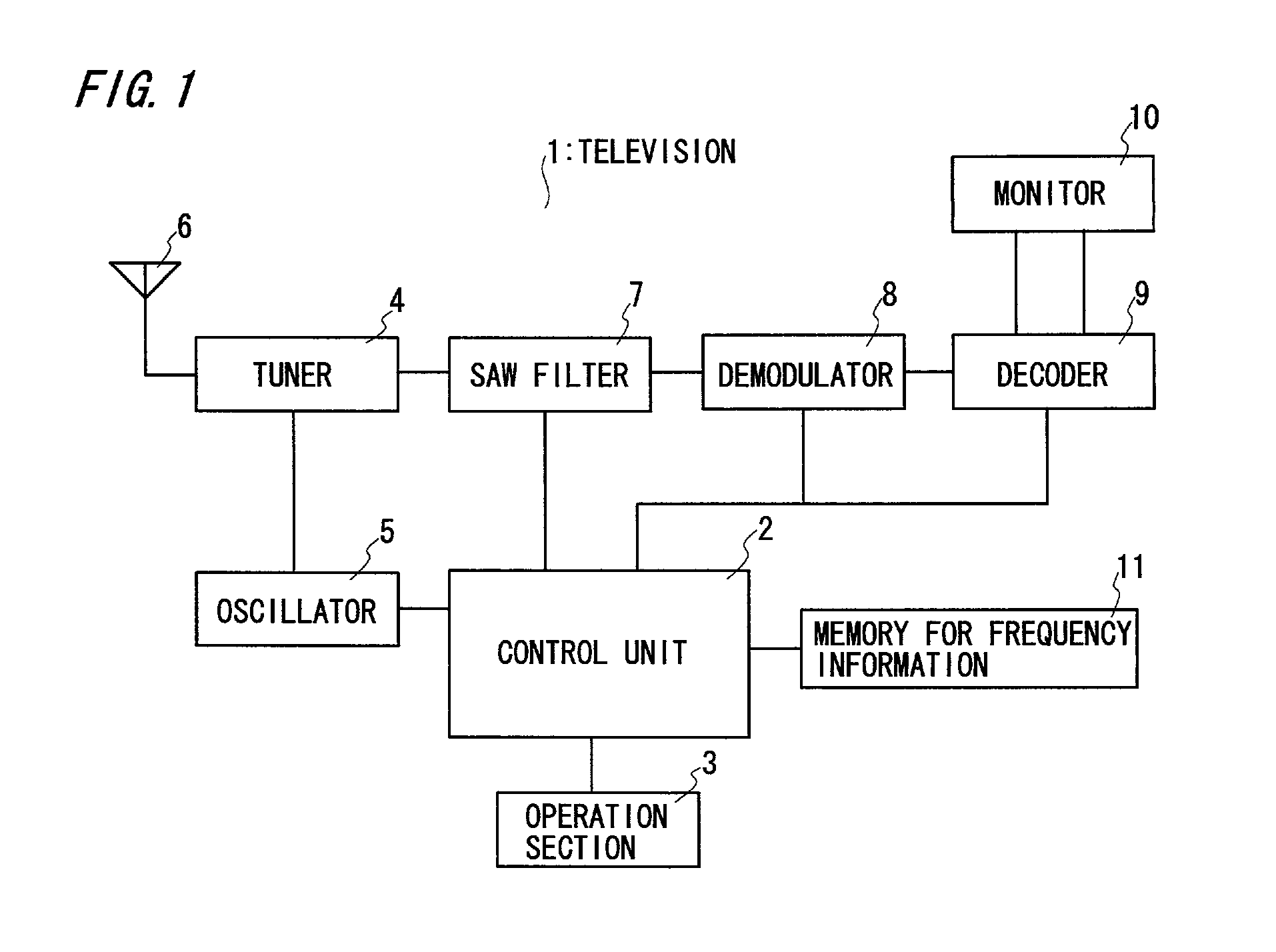
[0022]FIG. 1 shows a configuration of a high-definition television to which a receiving device of the invention is applied. A high-definition television 1 of this embodiment can be utilized in a U.S.A. ground-wave digital television system (ATSC system).

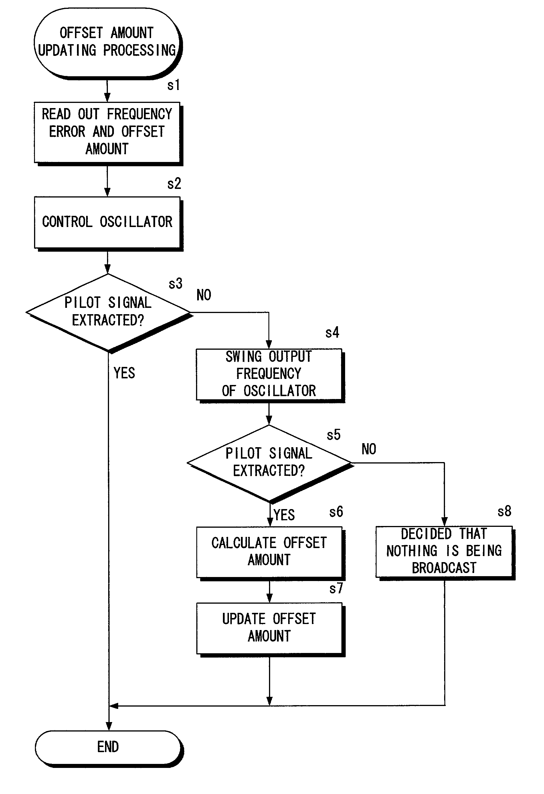
[0023]The operations of the high-definition television 1 are controlled by a control unit 2. An operation section 3 is adapted to, for example, select a reception channel. A tuner 4 is adapted to output an intermediate frequency signal (hereinafter refer to IF signal) obtained by tuning a radio signal received through an antenna 6 to an output signal of an oscillator 5. The signal received through the antenna 6 (receiver) contains a pilot signal. A SAW filter 7 is adapted to filter an IF signal output from the tuner 4 into a signal within a predetermined frequency band width. A demodulator 8 is adapted to perform A / D conversion on the IF signal filtered at the SAW filter 7 for providing a digital signal, and to extract the pilot sign...


PUM


Abstract

In a receiving device of the invention used in high-definition television, a frequency information storage section stores error information of a frequency error of a signal output from an oscillator. A control unit controls the oscillator based on the error information stored in the frequency information storage section. In a simple configuration, it is, therefore, possible to shift, the frequency in a direction of tuning by a tuner, to thereby output the signal with an appropriate frequency from the oscillator without being influenced by an accuracy of the oscillator, thus to demodulate the received signal accurately. Accordingly, it can be avoided such a problem that no pilot signal is present in an IF signal within a predetermined band width filtered by a SAW filter or that the pilot signal, even if present, cannot be received.

Description

BACKGROUND OF THE INVENTION[0001]The invention relates to a receiving device used in radio communication for transferring a pilot signal and, more particularly to, a receiving device applied to a high-definition television.[0002]Conventionally, there has been such a communication method that transfers a pilot signal so that a receiving device can demodulate a received signal accurately. As well known, the pilot signal is used to detect a carrier wave accurately on the receiving device. For example, the high-definition television broadcasting employed in U.S.A. etc. utilizes this communication method of transferring the pilot signal mentioned above.[0003]Conventional high-definition television is equipped with an oscillator for outputting a signal having a frequency which corresponds to a currently selected channel. A tuner outputs a signal of an intermediate frequency (hereinafter refer to IF signal) which is obtained by tuning a radio wave received through an antenna to an output s...

Claims


Application Information

Patent Timeline
Patent Type & Authority Patents(United States)
IPC IPC(8): H04N5/50H03J7/02H03J7/04H04B1/16H04N5/44H04N5/455
CPCH04N5/50H03J7/04H04N21/4263
Inventor WASHINO, TAKAO
Owner FUNAI ELECTRIC CO LTD
Why Eureka
Try Eureka