Apparatus and method for activating an inductance loop vehicle detection system
- Summary
- Abstract
- Description
- Claims
- Application Information
AI Technical Summary
Benefits of technology
Problems solved by technology
Method used
Image
Examples
Embodiment Construction
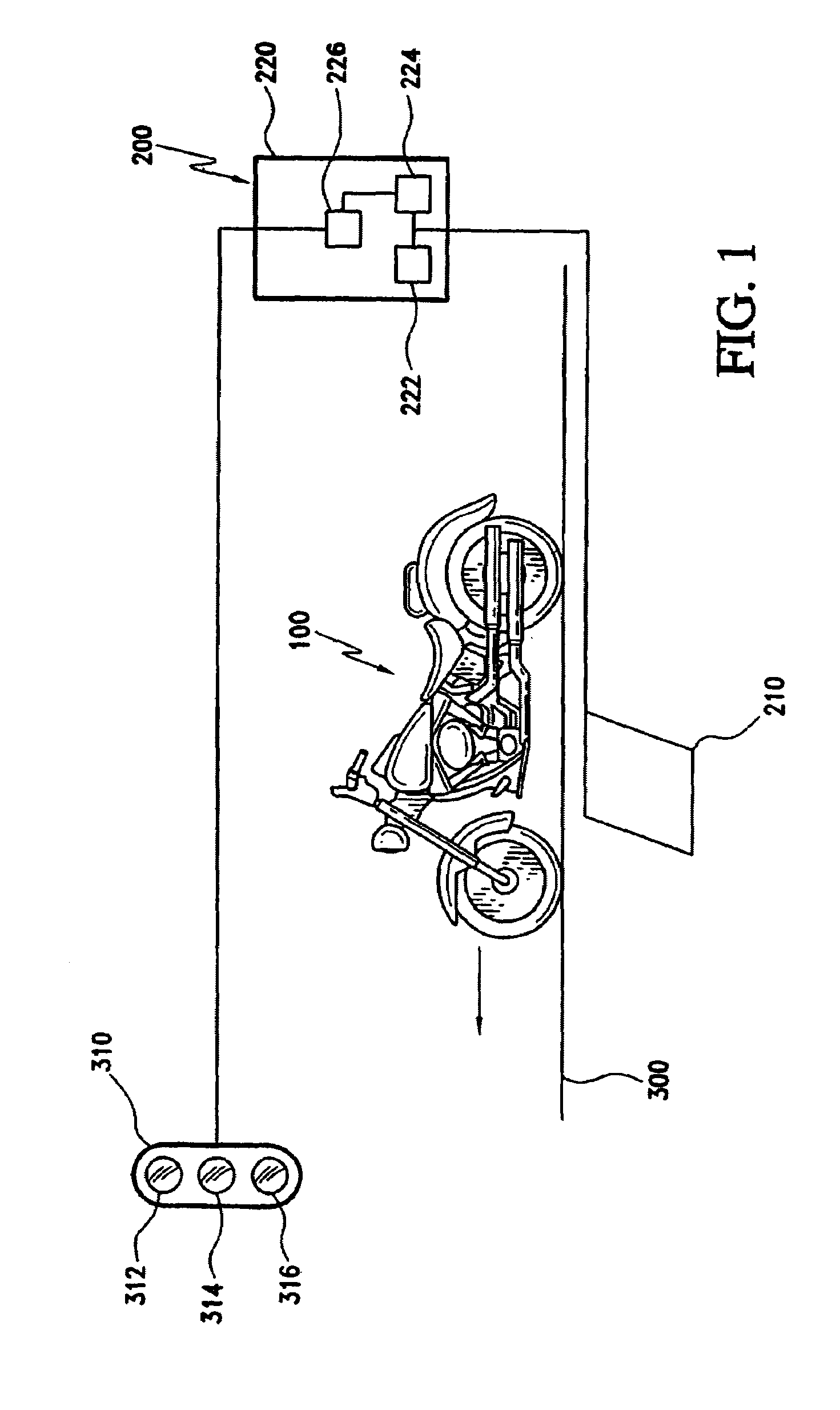
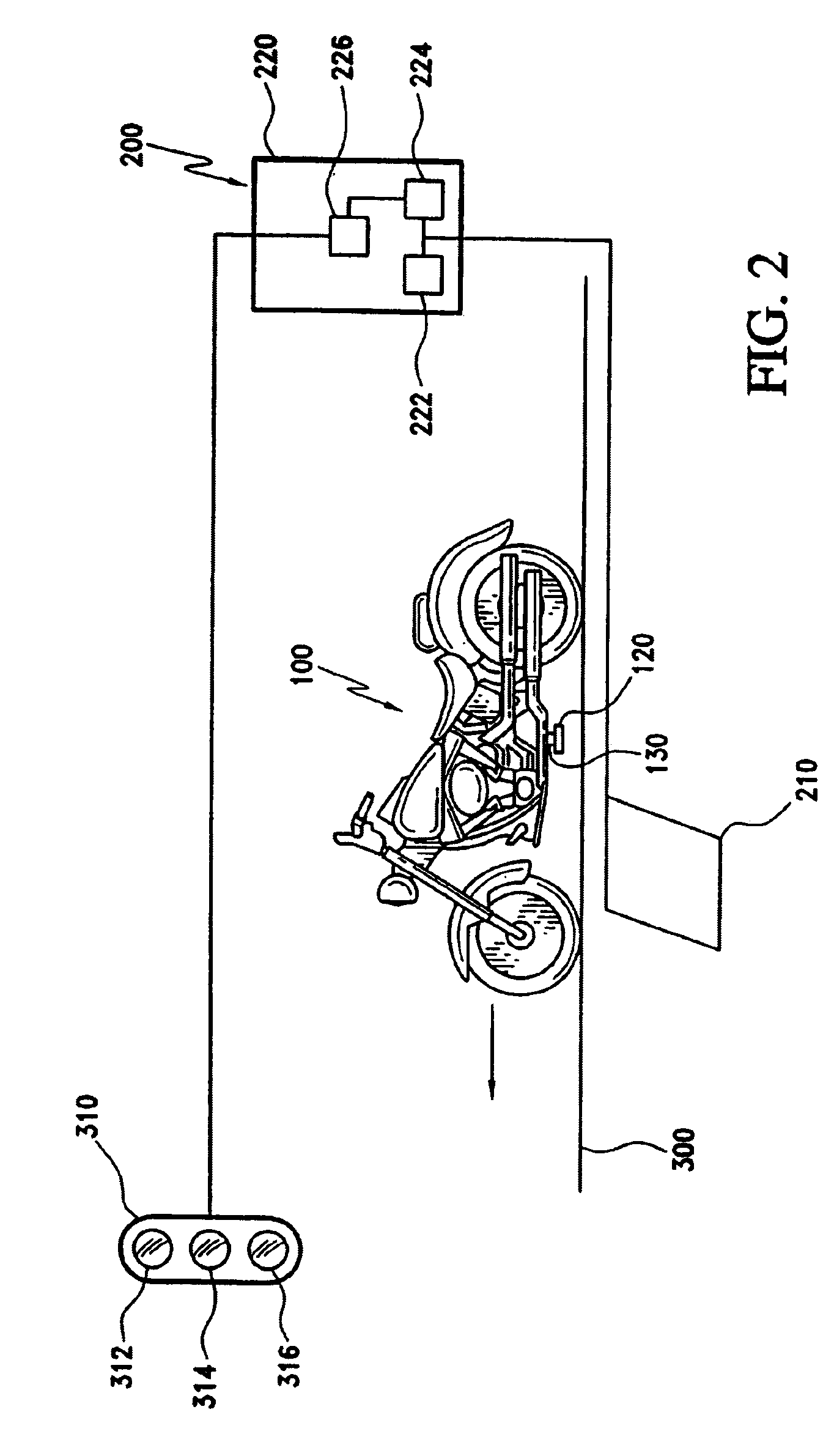
[0016]FIG. 1 depicts a vehicle 100 passing over an inductance loop 210 that is embedded in a roadway 300. Vehicle 100 is depicted as a motorcycle, but may be any type of vehicle, including an automobile, motorized scooter, or bicycle. Vehicle detection system 200 includes an inductance loop 210 and a control unit 220. Inductance loop 210 may be any type of inductance loop conventionally used for vehicle detection applications. Control unit 220 is connected to inductance loop 210 and includes one or more oscillators 222, an oscillation counter 224, and a traffic signal controller 226. Traffic signal controller 226 is connected to traffic signal 310 and controls the configuration of the traffic signal's red light 312, yellow light 314, and green light 316. Of course, those of ordinary skill in the art will appreciate that other types of traffic signals may employ different light colors and configurations (e.g., changing from a solid yellow light to a blinking yellow light in the prese...
PUM
 Abstract
Description
Claims
Application Information
 - R&D
- Intellectual Property
- Life Sciences
- Materials
- Tech Scout
- Unparalleled Data Quality
- Higher Quality Content
- 60% Fewer Hallucinations
Browse by: Latest US Patents, China's latest patents, Technical Efficacy Thesaurus, Application Domain, Technology Topic, Popular Technical Reports.
© 2025 PatSnap. All rights reserved.Legal|Privacy policy|Modern Slavery Act Transparency Statement|Sitemap|About US| Contact US: help@patsnap.com


