
Device for attaching return springs in a harness of a Jacquard weaving machine

a technology of return springs and weaving machines, which is applied in the direction of weaving, textiles and papermaking, dobbies, etc., can solve the problems of no longer being in correspondence with the pitch, the return spring position becomes uncertain, and the friction in the harness will increase, and the hooking together is difficul

Inactive Publication Date: 2006-04-11
N V MICHEL VAN DE WIELE
View PDF20 Cites 14 Cited by
  • Summary
  • Abstract
  • Description
  • Claims
  • Application Information

AI Technical Summary

Benefits of technology

[0012]Furthermore, an additional purpose of the invention is to be able to position the return spring exactly on the flat bars, without the position being changed during transport or operating conditions.
[0034]By directly installing the retaining means in the two fixed installing elements, the total height may be reduced and moreover the construction has a good deal less components which reduces the time for installation and the price.

Problems solved by technology

This design has the disadvantage, that the return springs which have been installed on the flat bar next to one another, are not self-gripping what causes the return springs to loose their exact positions, each time the harness is released and because of this the position of the return springs in the warp direction becomes uncertain and no longer in correspondence with the pitch of the cumber board.
Because of this, friction in the harness will increase or it may lead to a hooking together of the springs in case of major dimensional deviations.
When the foremost return springs are shifting forward too far they may collide with the reed.
This has the disadvantage that replacement on site becomes very difficult.
However this design has the disadvantage that a large variety of spacers are required with different thicknesses requiring quite some work for installation.
Here, replacements on site are also labor-intensive.
The disadvantage of this method is that a large number of parts have to be overmoulded simultaneously.
Besides, this production method is hardly flexible and replacement on site becomes very difficult.

Method used


Image

  • Device for attaching return springs in a harness of a Jacquard weaving machine
  • Device for attaching return springs in a harness of a Jacquard weaving machine
  • Device for attaching return springs in a harness of a Jacquard weaving machine

Examples


first embodiment

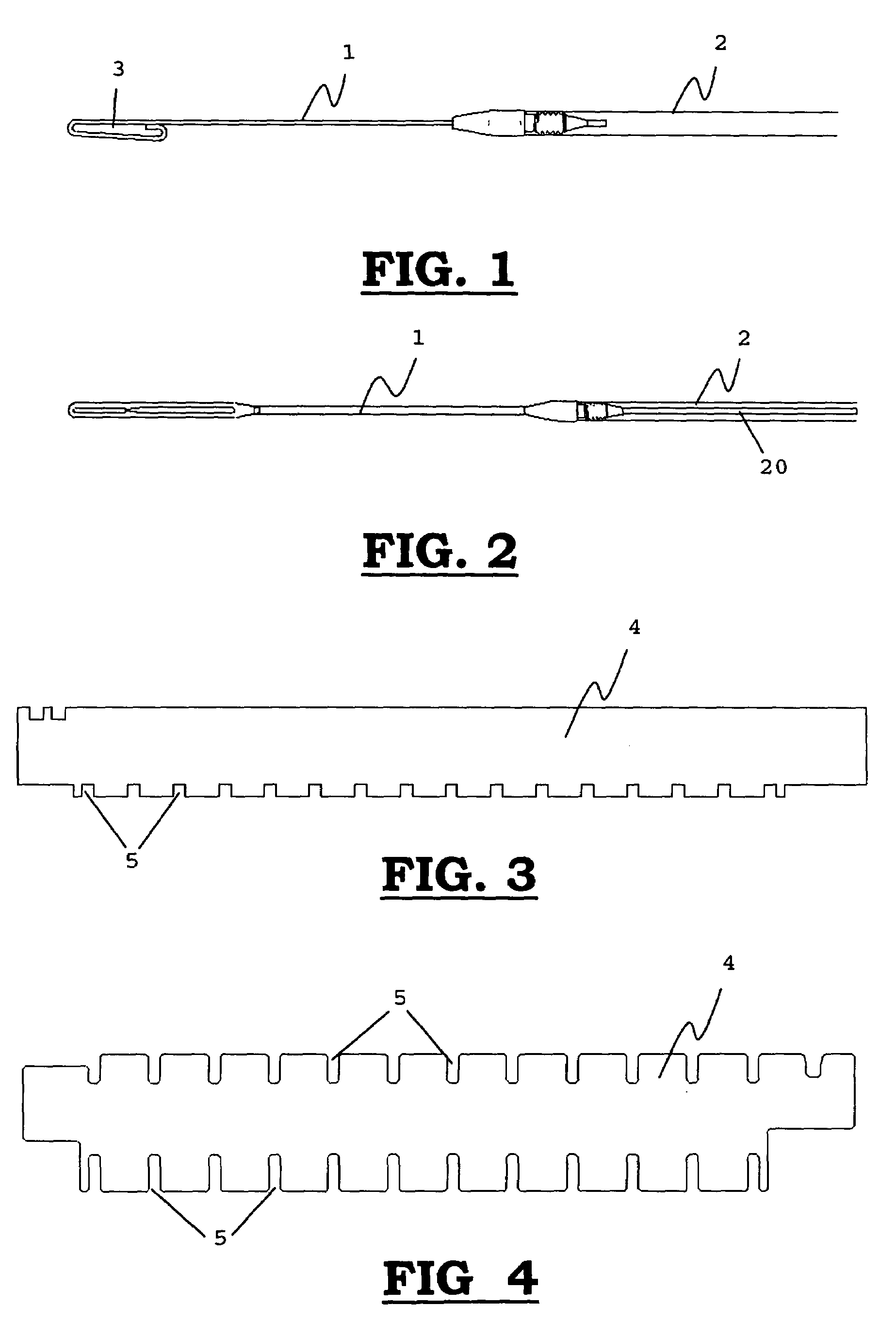
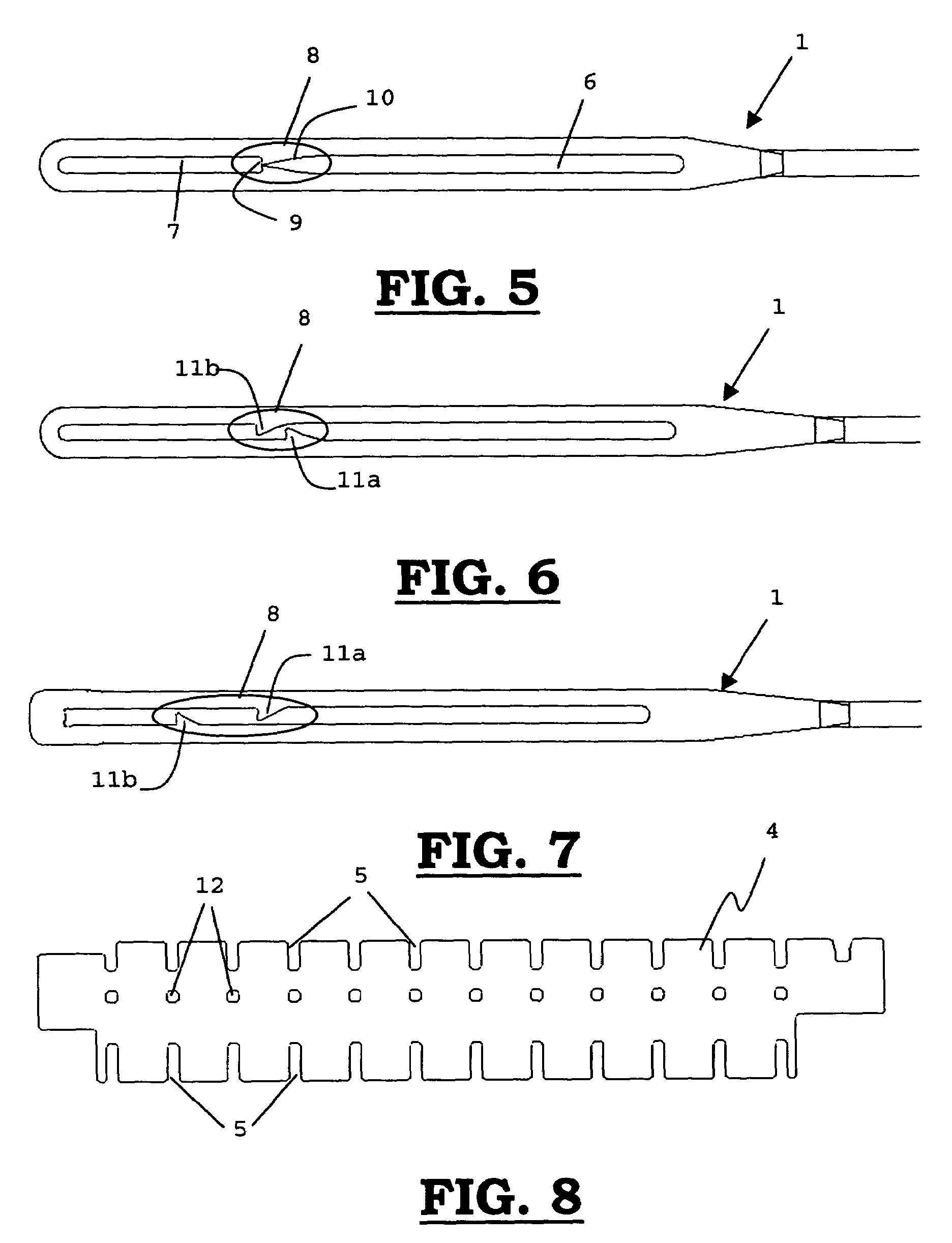
[0055]In the means of attachment (1) for attaching a return spring (2) to a flat bar (4) in a Jacquard weaving machine, this spring connection (8) is realized by providing a sharp and practically flat edge (9) in the fixing opening (7). Consequently, the means of attachment (1) will be unable to move from the fixing opening (7) to the positioning opening (6) with respect to the flat bar (4) during operation or transport of the Jacquard machine. In order to guide the motion of the means of attachment (1) from the positioning opening (6) to the fixing opening (7) with respect to the flat bar (4), a beveled edge (10) is provided in the positioning opening (6).

second embodiment

[0056]In a spring connection (8) according to the invention, as represented in FIG. 6, two protrusions situated opposite one another, an upper (11a) and a lower (11b) protrusion, have been provided, together forming a kind of labyrinth. The purpose of this labyrinth is to make it yet more difficult for the means of attachment (1) to become detached with respect to the flat bar (4) during operation or transport of the Jacquard machine.

third embodiment

[0057]In a spring connection (8) according to the invention, as represented in FIG. 7, the two protrusions (11a, 11b) of the labyrinth are moved further apart from one another. The upper protrusion (11a) is able to engage a recess (12), which has been provided, in the flat bar (4), as represented in FIG. 8. In this manner, it is almost impossible for the means of attachment (1) to become detached with respect to the flat bar (4) during operation or transport of the Jacquard machine.

[0058]Preferably the means of attachment (1) are made of synthetic material.

[0059]The flat bars (4) are carried out such that they may be immovably installed in a simple manner in the Jacquard weaving machine. Each flat bar (4) is inserted in two installing elements in the shape of a set of tubes (13) as represented in FIG. 9. These tubes (13) are provided with one or several grooves into which one or several flat bars (4) may be slid. Because of this, each flat bar (4) may take up an exact position in th...


PUM


Abstract

On the one hand, the invention relates to a device for exerting a return force on at least one harness element of the harness of a Jacquard weaving machine, comprising at least one return spring (2) provided with means of attachment (1) for attaching the return spring (2) to retaining means (4) being immovably provided, said means of attachment (1) being provided with a positioning opening (6) for positioning the means of attachment (1) with respect to the retaining means (4), and a fixing opening (7) for fixing the means of attachment (1) to the retaining means (4), a spring connection (8) being provided between the positioning opening (6) and the fixing opening (7), in such a manner that the means of attachment (1) are able to move from positioning opening (6) to the fixing opening (7) with respect to the retaining means (4), but after having been fixed will be unable to move back from the fixing opening (7) to the positioning opening (6) with respect to the retaining means during operation or transport of the Jacquard machine.On the other hand, the invention relates to a device for immovably installing the retaining means (4) of one or several return springs (2) of a Jacquard weaving machine, the device being provided with at least two fixed installing elements (13) for installing the retaining means (4), the said installing elements (13) being provided with one or several recesses to apply the retaining means (4).

Description

[0001]This application claims the benefit of Belgian Application No. 2002 / 0451 filed Jul. 19, 2002.BACKGROUND OF THE INVENTION[0002]On the one hand, the invention relates to a device for exerting a return force on at least one harness element of the harness of a Jacquard weaving machine, comprising at least one return spring provided with means of attachment in order to attach the return spring to retaining means immovably provided. On the other hand, the invention relates to a device for immovably installing the retaining means of one or several return springs of a jacquard weaving machine, the device being provided with at least two fixed installing elements for installing the retaining means.[0003]In a Jacquard machine, one or several return springs are applied at the bottom of the harness, in order to tighten the Jacquard heddle, the harness cord, the tackles, the tackle cords and the two complementary hooks, so that the noses of the hooks will be kept permanently in touch with ...

Claims


Application Information

Patent Timeline
Patent Type & Authority Patents(United States)
IPC IPC(8): D03C3/00D03C3/14D03C3/44D03C13/00
CPCD03C3/44
Inventor VANDERJEUGT, BRAMLAUWEREYS, YVAN
Owner N V MICHEL VAN DE WIELE
Learn More