
Fiber distribution frame arrangement having a centralized controller which universally controls and monitors access to fiber distribution frames

a technology of fiber distribution frame and centralized controller, which is applied in the direction of instruments, building locks, construction, etc., can solve the problems of increasing the potential for inadvertent exposure of human personnel to optical radiation, and the condition may also be undetected

Inactive Publication Date: 2006-04-04
SBC KNOWLEDGE VENTURES LP
View PDF7 Cites 13 Cited by
  • Summary
  • Abstract
  • Description
  • Claims
  • Application Information

AI Technical Summary

Benefits of technology

"The present invention is a fiber distribution frame arrangement with a centralized controller that monitors and controls access to fiber distribution frames. The controller can lock and unlock the doors of the fiber distribution frames using actuators positioned on the doors. The controller can also provide notification and alarms when a door is opened without permission. The technical effect of this invention is to provide a secure and automated means of securing fiber distribution frames, with a centralized controller that can control and monitor access to the frames."

Problems solved by technology

As the amplification factor of the optical signals communicated by the fiber optic components deployed within a fiber distribution frame increases, so increases the potential for inadvertent exposure by human personnel to optical radiation.
At times, this may be problematic because a fiber distribution frame may have many doors and, consequently, a door may be inadvertently left open with this condition being undetected for some time.
Consequently, if the door(s) of the fiber distribution frames located in remote areas are inadvertently left open, this condition may also be undetected for some time.

Method used


Image

  • Fiber distribution frame arrangement having a centralized controller which universally controls and monitors access to fiber distribution frames
  • Fiber distribution frame arrangement having a centralized controller which universally controls and monitors access to fiber distribution frames

Examples


Embodiment Construction

)

[0010]The advantages of the fiber distribution frame arrangement in accordance with the present invention are numerous. For example, the fiber distribution frame arrangement provides an automated and mechanized means of securing “at risk” locations; provides suitable alarming; and provides visual and audible notifications of at risk locations for human optical protection.

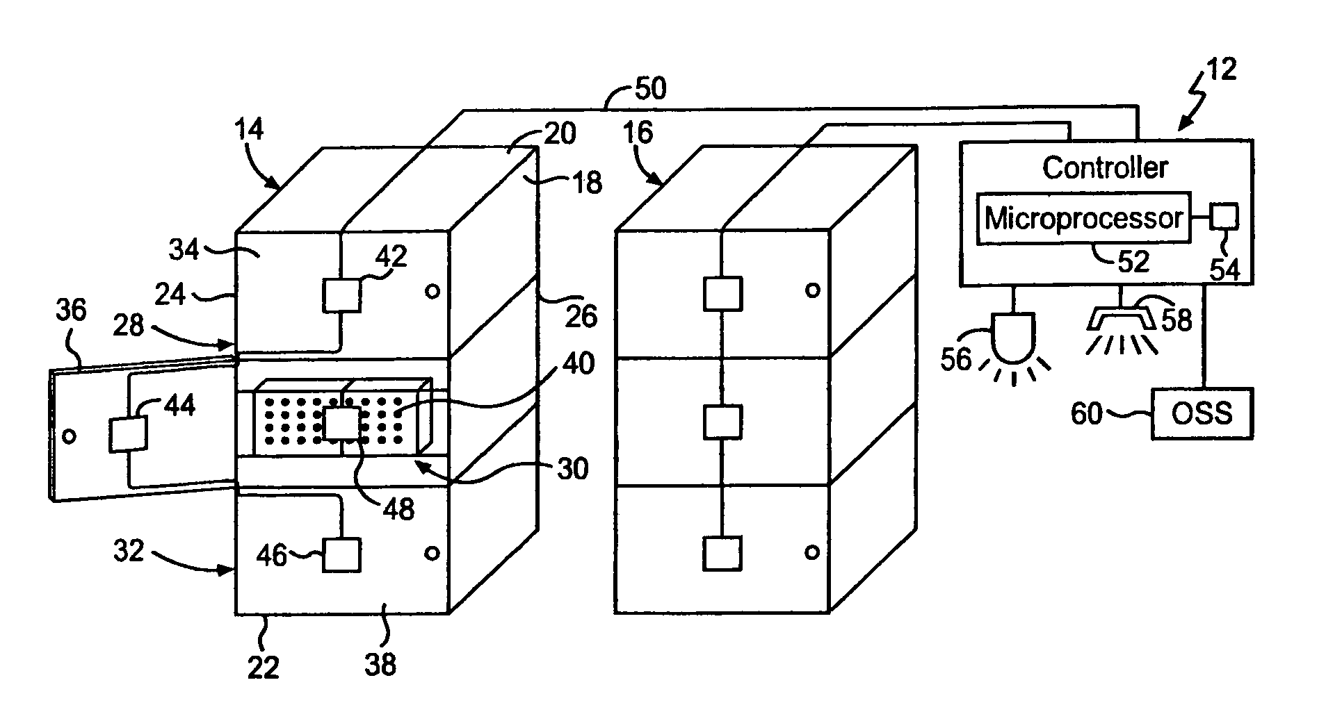
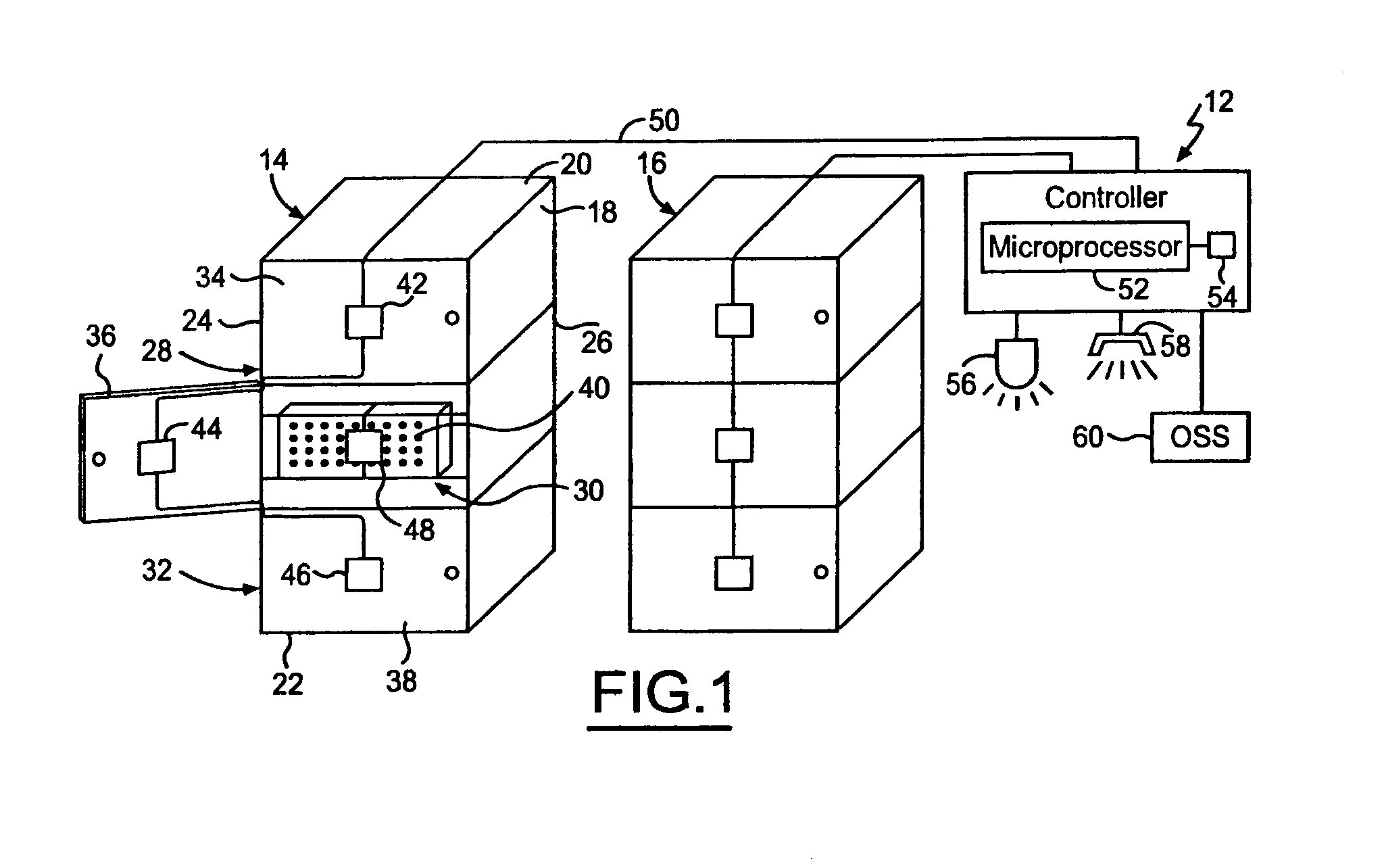
[0011]The fiber distribution frame arrangement in accordance with the present invention has a centralized controller which universally controls and monitors access to panels and doors of the fiber distribution frames present in the arrangement. The controller enables all the doors of each fiber distribution frame to be closed and locked with the push of a button in order to prevent the panels of the fiber distribution frame from being exposed. The doors of a fiber distribution frame are universally cabled to the controller to permit the immediate lock-down of the panels in the fiber distribution frame when fiber op...


PUM


Abstract

A fiber distribution frame arrangement includes a fiber distribution frame. Fiber optic component panels are housed within the fiber distribution frame at respective positions. Doors are connected to the fiber distribution frame for the doors to open and close relative to the fiber distribution frame. Each door corresponds to one of the fiber optic component panels such that the door opens and closes relative to the corresponding fiber optic component panel when the door opens and closes relative to the fiber distribution frame. Actuators corresponding to the doors are positioned on the corresponding doors in order to lock the corresponding door to the fiber distribution frame upon actuation when the corresponding door is closed. A cable extends between each actuator for connecting the actuators together. A controller communicates with the actuators via the cable in order to control actuation of the actuators and monitor actuation status of the actuators.

Description

BACKGROUND OF THE INVENTION[0001]1. Field of the Invention[0002]The present invention generally relates to fiber distribution frames and, more particularly, to a fiber distribution frame arrangement having a centralized controller which universally controls and monitors access to fiber distribution frames.[0003]2. Background Art[0004]A fiber distribution frame serves as an interface between outside plant fiber optic facilities entering a central office structure and fiber optic equipment installed within that same location. The fiber distribution frame provides a centralized point for the organization and administration of the fiber optic facility and intra-building fiber equipment cables; provides a flexible platform for future fiber growth; and provides re-configurable connections between any two terminations or appearances.[0005]In its most basic form, a fiber distribution frame is a housing, cabinet, enclosure, etc., which houses fiber optic components. Fiber optic components in...

Claims


Application Information

Patent Timeline
Patent Type & Authority Patents(United States)
IPC IPC(8): G02B6/00
CPCG02B6/4452G02B6/44526
Inventor WEINERT, STEPHEN J.YEILDING, MICHAEL L.LANGLEY, JEFFREY LYNN
Owner SBC KNOWLEDGE VENTURES LP
Learn More