Methods and apparatus for operating a speedcooking oven

a technology for speedcooking ovens and ovens, applied in electrical apparatus, microwave heating, electric/magnetic/electromagnetic heating, etc., can solve the problems of ovens, ovens, ovens, etc., which may not be as fast as radiant or microwave ovens, and can not be used in microwave cooking modes

Inactive Publication Date: 2006-04-04
HAIER US APPLIANCE SOLUTIONS INC
View PDF11 Cites 14 Cited by
  • Summary
  • Abstract
  • Description
  • Claims
  • Application Information

AI Technical Summary

Benefits of technology

[0005]One way to achieve speedcooking in an oven is to include both microwave and radiant energy sources, and convection. The combination of microwave and radiant energy sources facilitates fast cooking of foods. In addition, and as compared to microwave only cooking, a combination of microwave and radiant energy sources can cook a wider variety of foods.

Problems solved by technology

Radiant ovens, however, cook many foods slower than microwave ovens.
Such ovens, however, may not cook as fast as radiant or microwave ovens.
When the door frame is fabricated from a metallic material which is in direct contact with the glass window problems can arise in the microwave cooking modes.
For example, if the microwave fields are relatively large in the vicinity of the glass / metal interface, excessive heating may occur causing the glass to crack.
The microwave can also generate relatively large microwave fields which may induce arcing through the glass, again damaging the glass.
In addition, a glass to metal interface can be the source of large thermally induced stress during the high temperatures needed for the self clean cycle.
Other problems may occur if the metal to glass interface is not sufficiently tight.
For example, the glass may move freely in the glass / metal interface allowing mechanical damage to occur to the glass during shipping or moving.
In addition a seal will not be formed between the cooking cavity and door components beyond the inner glass and door allowing cooking vapors, moisture and gases to escape the cooking cavity thereby reducing visibility and lowering performance of the oven.

Method used


Image

  • Methods and apparatus for operating a speedcooking oven
  • Methods and apparatus for operating a speedcooking oven
  • Methods and apparatus for operating a speedcooking oven

Examples


Embodiment Construction

[0022]In the exemplary embodiment, the methods and apparatus described herein are applicable to the operation of an oven that includes sources of radiant and microwave energy as well as a convection heating element, a bake heating element, and a broiler heating element. Although three specific embodiments of such an oven are described herein, it should be understood that the present invention can be utilized in combination with many other such ovens and is not limited to practice with the ovens described herein. For example, one oven described herein below is a speedcook oven including a range. The present invention, however, is not limited to practice with just full-size ovens that include a rangetop, but can be used with many other types of ovens such as countertop or built-in wall ovens, over the range type ovens, and a double wall oven.

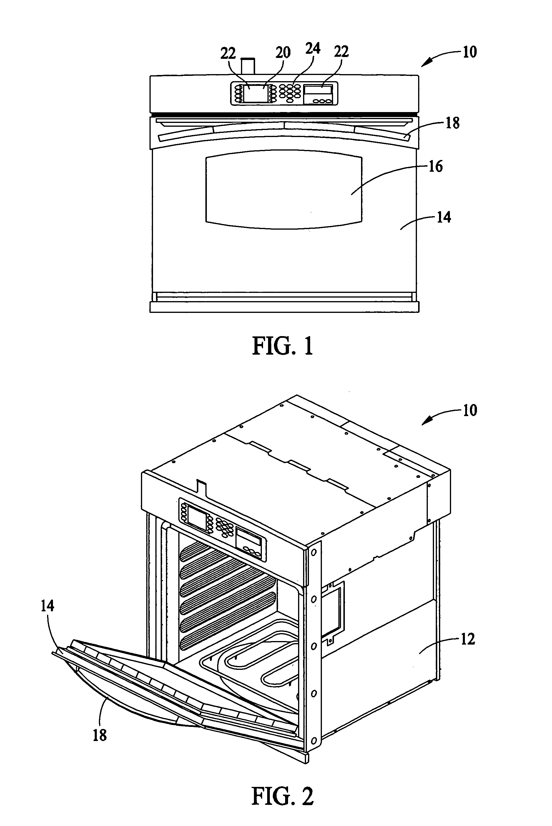
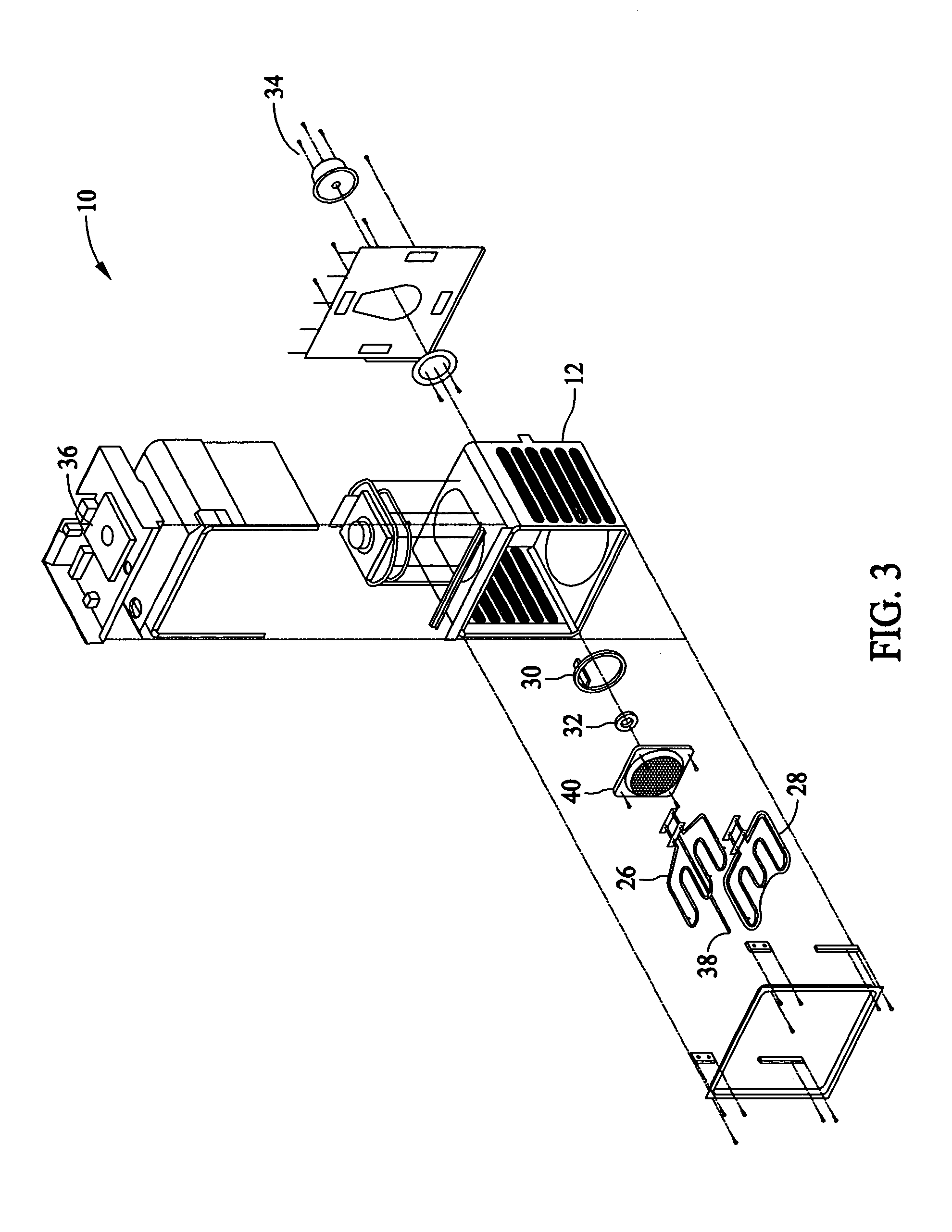
[0023]FIG. 1 is a front view of a speedcook oven 10. FIG. 2 is a perspective view of speed cook oven 10. FIG. 3 is an exploded view of the oven s...


PUM


Abstract

A microwave choke assembly includes a microwave choke, a glass capture channel coupled to the microwave choke, and a gasket positioned at least partially within the glass capture channel, the glass capture channel and a window separated by a first distance.

Description

[0001]This invention relates generally to ovens and, more particularly, to an oven operable in speedcooking, microwave, and convection / bake modes.[0002]Ovens typically are either, for example, microwave, radiant, or thermal / convection cooking type ovens. For example, a microwave oven includes a magnetron for generating RF energy used to cook food in an oven cooking cavity. Although microwave ovens cook food more quickly than radiant or thermal / convection ovens, microwave ovens do not brown the food. Microwave ovens therefore typically are not used to cook as wide a variety of foods as radiant or thermal / convection ovens.[0003]Radiant cooking ovens include an energy source such as lamps or resistive sheath elements which generate radiant energy used to cook the food. Radiant ovens brown the food and generally can be used to cook a wider variety of foods than microwave ovens. Radiant ovens, however, cook many foods slower than microwave ovens.[0004]In thermal / convection ovens, the foo...

Claims


Application Information

Patent Timeline
IPC IPC(8): H05B6/76
CPCH05B6/763
Inventor BAKANOWSKI, STEPHEN MICHAELKINNY, DAVID LAURENCETARR, RONALD SCOTTPORTARO, LAWRENCE MICHAELBARGALE, SUKUMAR DHANPAL
Owner HAIER US APPLIANCE SOLUTIONS INC
Why Eureka
Try Eureka