
Method for on-site treatment of oil and gas well waste fluids

a technology for oil and gas wells and waste fluids, which is applied in the direction of treatment water, separation process, borehole/well accessories, etc., can solve the problems of uneconomical offsite treatment limited options for responsible parties associated with drilling operations, and high cost of drilling waste fluids. , to achieve the effect of reducing the chance of groundwater contamination, reducing the ph of fluid waste, and eliminating the high cos

Inactive Publication Date: 2006-04-04
FLUID RECOVERY SERVICES
View PDF39 Cites 43 Cited by
  • Summary
  • Abstract
  • Description
  • Claims
  • Application Information

AI Technical Summary

Benefits of technology

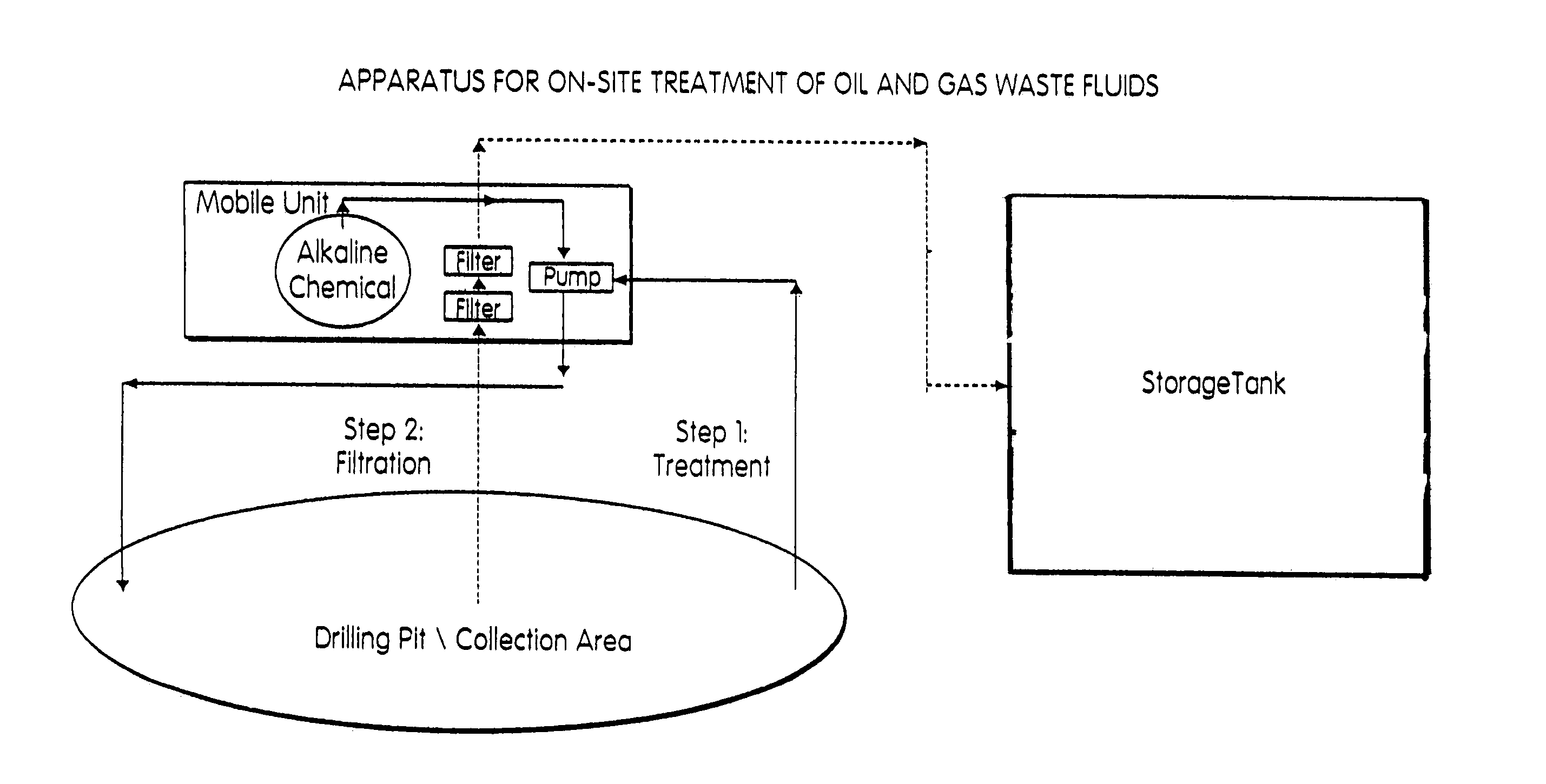
[0011]In accordance with the present invention, on-site treatment of drilling waste fluids from oil and gas well operations is provided through a mobile apparatus that treats waste fluids in drilling pits and permits and allows for reuse of the treated fluids in future drilling operations.
[0012]The mobile treatment process and apparatus of the present invention are designed to work at the drilling pit or other waste fluid collection areas associated with oil and gas well drilling operations and, more specifically, the drilling fluid wastes which are deposited within these drilling pits or collection areas. In general, the mobile treatment process and apparatus of the present invention provides both chemical precipitation and filtration to treat the drilling fluid waste to a technically and environmentally acceptable level allowing for reuse. More specifically, alkaline treating agents are applied to the drilling waste fluids, as they are pumped through the treatment apparatus, to increase the pH of the fluid waste to a preferred pH range and to also cause selective soluble contaminants in the fluids to form a precipitate. After the addition of this alkaline agent, the waste fluid is allowed to clarify as the precipitate of insoluble contaminants, through flocculation, settle and form a sludge at the bottom of the drilling pit. The clarified fluids are then filtered to satisfy applicable industry and environmental requirements.
[0013]The treated fluid waste may thereafter be used in new drilling operations at the same or other drilling sites. On-site treatment of the drilling fluid waste, as provided by the present invention, eliminates the high cost associated with transporting fluid waste to an offsite reclamation or disposal facility. Waste water treatment, in the fluid waste collection areas (e.g., drilling pits), also reduces the chance of groundwater contamination and provides reusable water, for use in new drilling operations, at a lower cost.

Problems solved by technology

Depending upon applicable environmental requirements, responsible parties associated with drilling operations have had limited options in respect to clean up of drilling pits and related fluid waste products.
In states with more stringent environmental requirements, such as Pennsylvania, the responsible party associated with the drilling operations typically is forced to incur the expense of transporting the fluid waste products in the drilling pits to a properly licensed disposal site and / or reclamation operation.
Offsite treatment of drilling waste fluids is uneconomical, however, because of the transportation costs associated in transporting the fluid waste to a reclamation or treatment area.
In particular, absent permitted reuse of the drilling fluid waste products, the drilling operator is required to use new, fresh water for ongoing drilling operations.
In the absence of a ready source for such fresh water, or in drought conditions, the drilling operator is required to bring water on-site for the continuing drilling operations, which again involves a high trucking cost for the movement of water.
The prior art reveals several efforts to address this need, however, these efforts continue to involve high economic costs and / or do not satisfy strict environmental requirements that exist for fluid reuse in certain states.
While the water treated through the teachings of the '665 patent can be reused, the process taught by the '665 patent is much more expensive and time consuming than the present invention.

Method used


Image

  • Method for on-site treatment of oil and gas well waste fluids
  • Method for on-site treatment of oil and gas well waste fluids

Examples


Embodiment Construction

[0016]The present invention provides a mobile treatment process and apparatus for use in treating waste fluid products from oil and natural gas drilling operations. In particular, the mobile treatment apparatus is positioned to treat the drilling fluid waste within fluid waste collection areas such as drilling pits through a multi-step process that includes chemical precipitation and filtration. After treatment using the process of the present invention, the resulting fluids can be reused in future drilling operations.

[0017]In a preferred embodiment, the on-site treatment of drilling fluid waste involves the steps of: (a) bringing a mobile treatment apparatus on-site to the waste collection area or drilling pit associated with an oil or gas well drilling operation and positioning the apparatus to allow the fluid waste to be pumped through the treatment apparatus and then back to the fluid waste collection area; (b) adding a alkaline agent to the waste fluid product as it is pumped t...


PUM

PropertyMeasurementUnit
Fractionaaaaaaaaaa
Timeaaaaaaaaaa
Timeaaaaaaaaaa

Abstract

An apparatus and method for on-site treatment and reclamation of oil and gas well waste water or fracturing fluids. The mobile treatment process and apparatus provide both chemical precipitation and filtration to treat the drilling fluid waste to a technically and environmentally acceptable level allowing for reuse. Alkaline treating agents are applied to the drilling waste fluids, as they are pumped through the treatment apparatus, to increase the pH of the fluid waste to a preferred pH range and to also cause selective soluble contaminants in the fluids to form a precipitate. The waste fluid is allowed to clarify as the precipitate of insoluble contaminants, through flocculation, settle and form a sludge at the bottom of the drilling pit. The clarified fluids are then filtered to satisfy applicable industry and environmental requirements.

Description

FIELD OF THE INVENTION[0001]This invention relates to a method for on-site treatment and reclamation of oil and gas well waste water or fracturing fluids. In a preferred embodiment, a mobile apparatus is used to chemically treat and filter waste fluids produced at oil and gas well drilling sites so that these fluids can be reused.BACKGROUND AND SUMMARY OF THE INVENTION[0002]It is well known that oil and gas well exploration involves the generation of waste water products, including fluid wastes in the nature of either drilling fluids or fracture or return fluids from the drilling operation. Typically, drilling pits are excavated by a well operator, near the drilling site, to receive these fluid waste products. Environmental clean-up requirements, imposed by the EPA and local government agencies, require the responsible party associated with the drilling operations to remediate the drilling site and, in particular, any drilling pits and related fluid waste products.[0003]Depending up...

Claims


Application Information

Patent Timeline
IPC IPC(8): B01D21/01C02F1/00C02F1/52C02F1/66
CPCC02F1/66C02F1/001C02F1/5236C02F2201/008C02F2103/34
Inventor HART, PAUL JOHNSNYDER, REBECCA K.
Owner FLUID RECOVERY SERVICES
Learn More