
Fibrillation/tachycardia monitoring and preventive system and methodology

a technology of tachycardia and monitoring system, applied in the field of implantable devices, can solve the problems of heart already reaching dangerous state, ventricles may not be able to fill with enough blood,

Inactive Publication Date: 2006-03-28
ELECTROHEALING HLDG
View PDF7 Cites 52 Cited by
  • Summary
  • Abstract
  • Description
  • Claims
  • Application Information

AI Technical Summary

Problems solved by technology

In such an instance, the ventricles may not be able to fill with enough blood to supply the body with the oxygen rich blood that it needs.
In other words, the heart has already reached a dangerous state before the conventional ICDs provide any stimulus to rectify the problem.

Method used


Image

  • Fibrillation/tachycardia monitoring and preventive system and methodology
  • Fibrillation/tachycardia monitoring and preventive system and methodology
  • Fibrillation/tachycardia monitoring and preventive system and methodology

Examples


Embodiment Construction

[0022]The present invention will be described in connection with preferred embodiments; however, it will be understood that there is no intent to limit the present invention to the embodiments described herein. On the contrary, the intent is to cover all alternatives, modifications, and equivalents as may be included within the spirit and scope of the present invention as defined by the appended claims.

[0023]For a general understanding of the present invention, reference is made to the drawings. In the drawings, like reference have been used throughout to designate identical or equivalent elements. It is also noted that the various drawings illustrating the present invention are not drawn to scale and that certain regions have been purposely drawn disproportionately so that the features and concepts of the present invention could be properly illustrated.

[0024]Current medical research has demonstrated that fibrillation has three detectable stages wherein some intervention is needed b...


PUM


Abstract

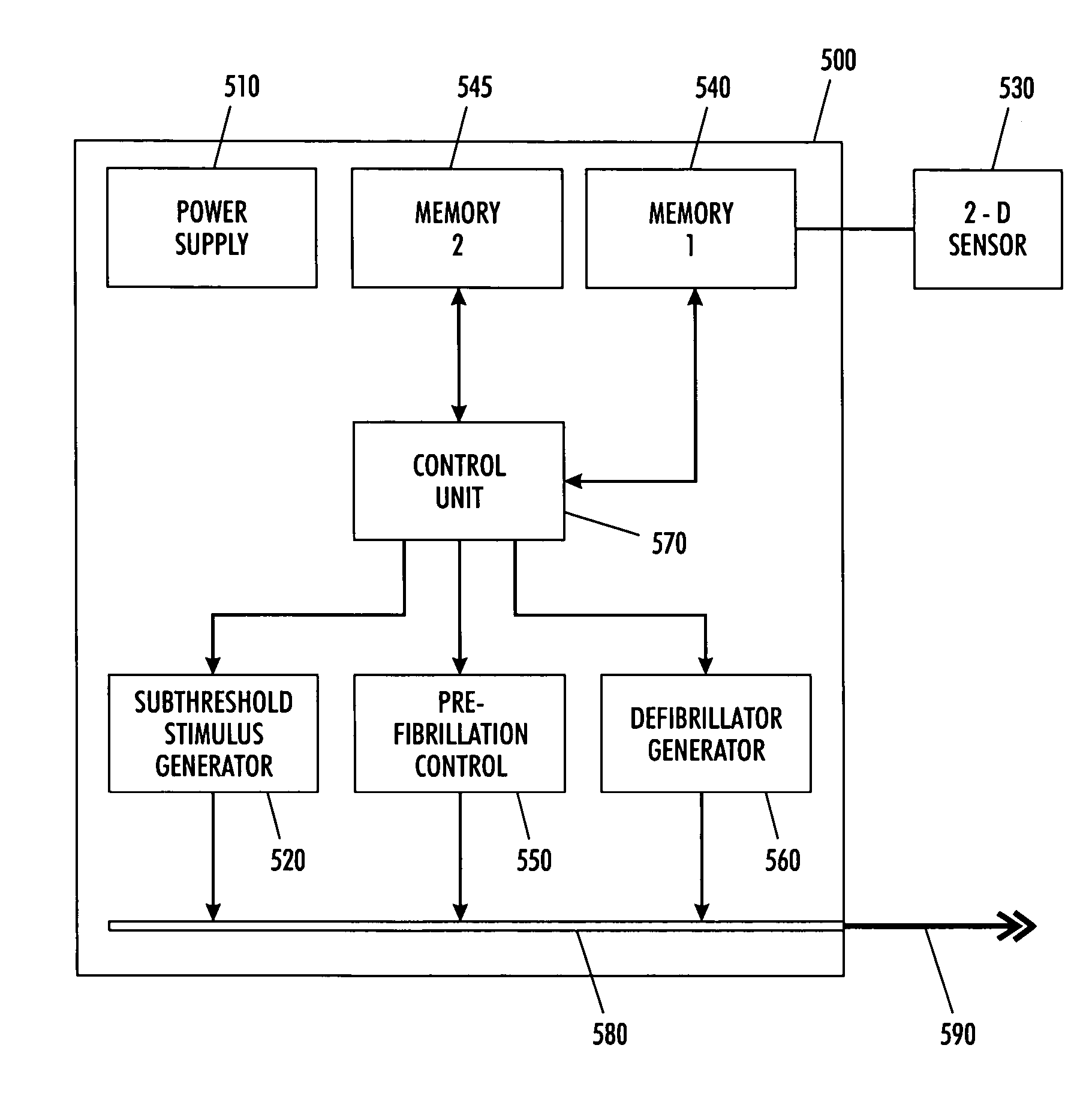
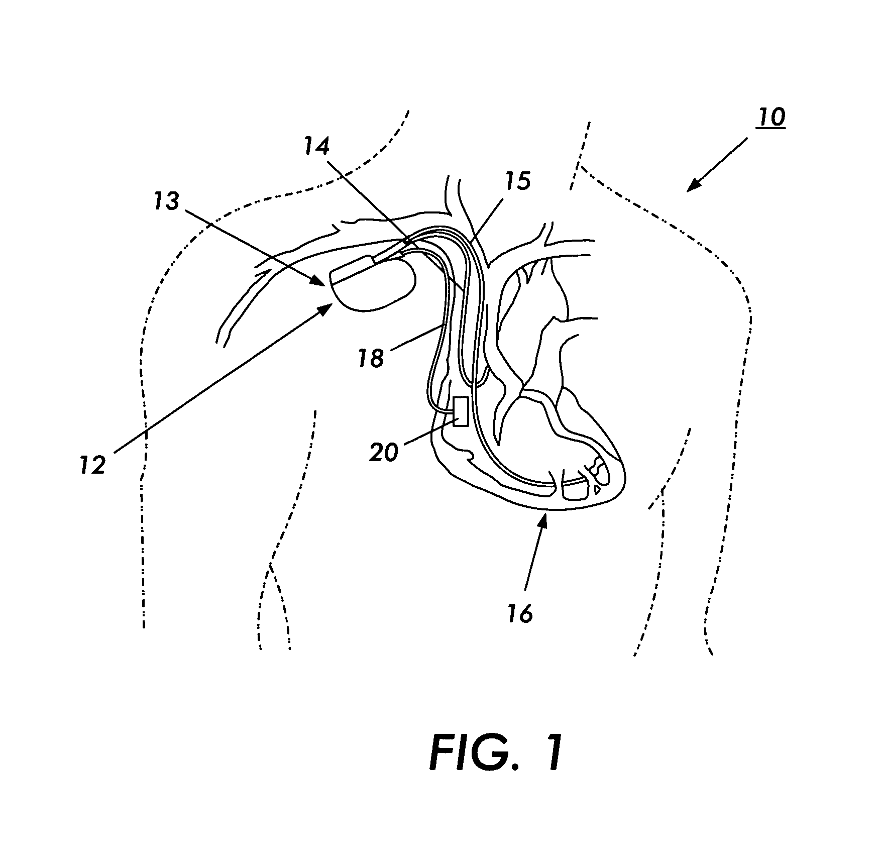
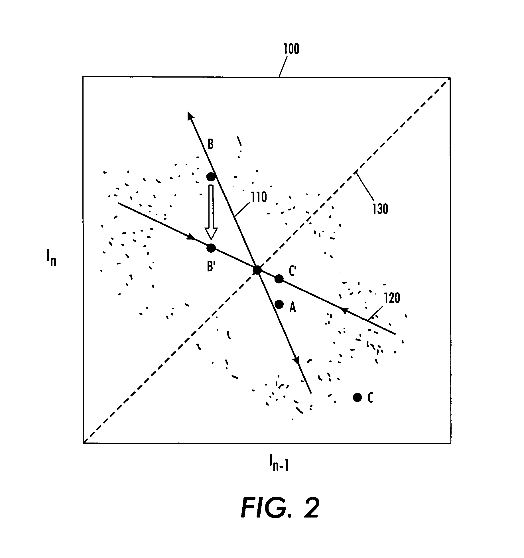
A cardiac assist device senses conditions of a heart and controls the generation of various electrical stimuli in response to sense conditions of the heart. The cardiac assist device generates a electrical pulse so as to defibrillate a fibrillated heart when the cardiac assist device determines from the sensed conditions a state of fibrillation. The cardiac assist device generates a chaos control electrical signal so as to bring a pre-fibrillated heart condition back into a normal beating condition when the cardiac assist device determines from the sensed conditions a pre-state of fibrillation. Lastly, the cardiac assist device generates an electrical enhancement signal that causes a threshold of pacing cells in the heart to be exceeded in response to a subthreshold stimulus when the cardiac assist device determines from the sensed conditions a subthreshold pacing signal.

Description

CROSS REFERENCE TO RELATED PATENT APPLICATIONS[0001]The subject matter of co-pending U.S. patent application Ser. No. 09 / 885,867, filed on Jun. 20, 2001, entitled “Controllable, Wearable MRI-Compatible Cardiac Pacemaker With Pulse Carrying Photonic Catheter And VOO Functionality”; co-pending U.S. patent application Ser. No. 09 / 885,868, filed on Jun. 20, 2001, entitled “Controllable, Wearable MRI-Compatible Cardiac Pacemaker With Power Carrying Photonic Catheter And VOO Functionality”; co-pending U.S. patent application Ser. No. 10 / 037,513, filed on Jan. 4, 2002, entitled “Optical Pulse Generator For Battery Powered Photonic Pacemakers And Other Light Driven Medical Stimulation Equipment”; co-pending U.S. patent application Ser. No. 10 / 037,720, filed on Jan. 4, 2002, entitled “Opto-Electric Coupling Device For Photonic Pacemakers And Other Opto-Electric Medical Stimulation Equipment”; co-pending U.S. patent application Ser. No. 09 / 943,216, filed on Aug. 30, 2001, entitled “Pulse Widt...

Claims


Application Information

Patent Timeline
Patent Type & Authority Patents(United States)
IPC IPC(8): A61N1/362A61N1/365A61N1/39
CPCA61N1/3622A61N1/3962A61N1/36542
Inventor WEINER, MICHAEL L.
Owner ELECTROHEALING HLDG
Learn More