
Code division multiple access signal receiving apparatus

a technology of multiple access signal and receiving apparatus, which is applied in the direction of coding, amplitude demodulation, code conversion, etc., can solve the problems of interference noise, poor power efficiency of non-directional antennas, and degrade communication quality, so as to improve the quality of the receive signal, increase the interference noise, and increase the noise

Inactive Publication Date: 2006-03-28
FUJITSU LTD
View PDF11 Cites 15 Cited by
  • Summary
  • Abstract
  • Description
  • Claims
  • Application Information

AI Technical Summary

Benefits of technology

[0018]Accordingly, an object of the present invention is to eliminate interference between signals due to momentary deterioration of a cross-correlation characteristic between spreading codes, thereby making high-quality reception possible.
[0020]In accordance with this code division multiple access signal receiving apparatus, if a cross-correlation value between spreading-code sequences increases and gives rise to an increase in interference noise, receive processing is executed upon excluding the symbol as a non-receive symbol in the interval of increased noise. As a result, an improvement in the quality of the receive signal becomes possible.

Problems solved by technology

However, not only is transmission by a non-directional antenna poor in power efficiency because radio waves are emanated also in directions in which a targeted mobile station is not present, but such transmission also degrades communication quality by subjecting mobile stations other than the targeted mobile station to interference.
In such cases, receive signals other than the desired receive signals received by the mobile stations become interference noise because the two transmit signals were spread-spectrum modulated by spreading-code sequences that differ from each other.
This brings about undesirable results, such as a decrease in system capacity (the number of users that can be accommodated)
Further, it is difficult to estimate the signal-to-noise ratio accurately on a per-symbol basis.
It is also difficult, therefore, to execute receive processing properly by detecting an increase in local interference noise in a specific symbol contained in a receive signal.

Method used


Image

  • Code division multiple access signal receiving apparatus
  • Code division multiple access signal receiving apparatus
  • Code division multiple access signal receiving apparatus

Examples


first embodiment

[0042](A) First Embodiment

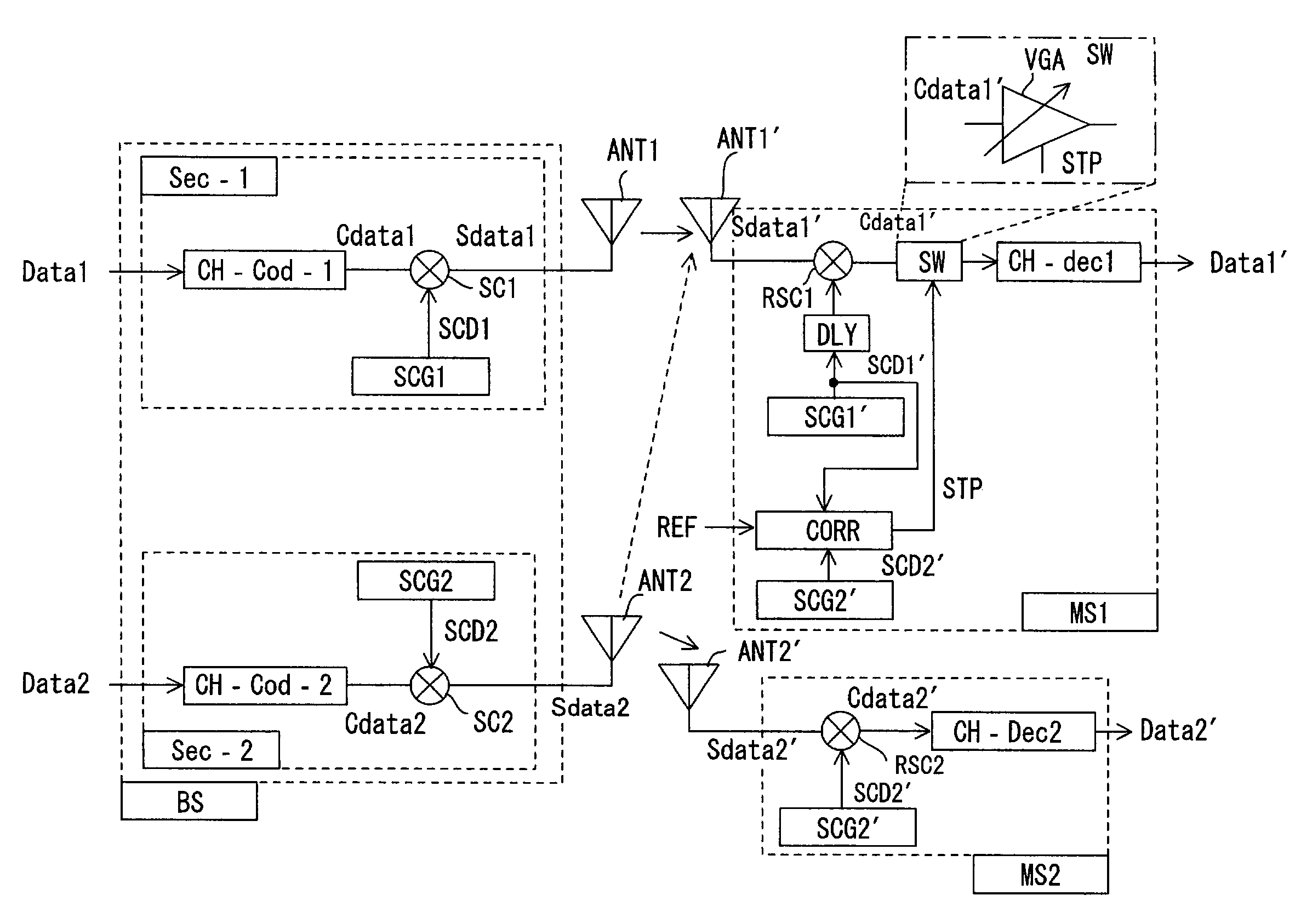
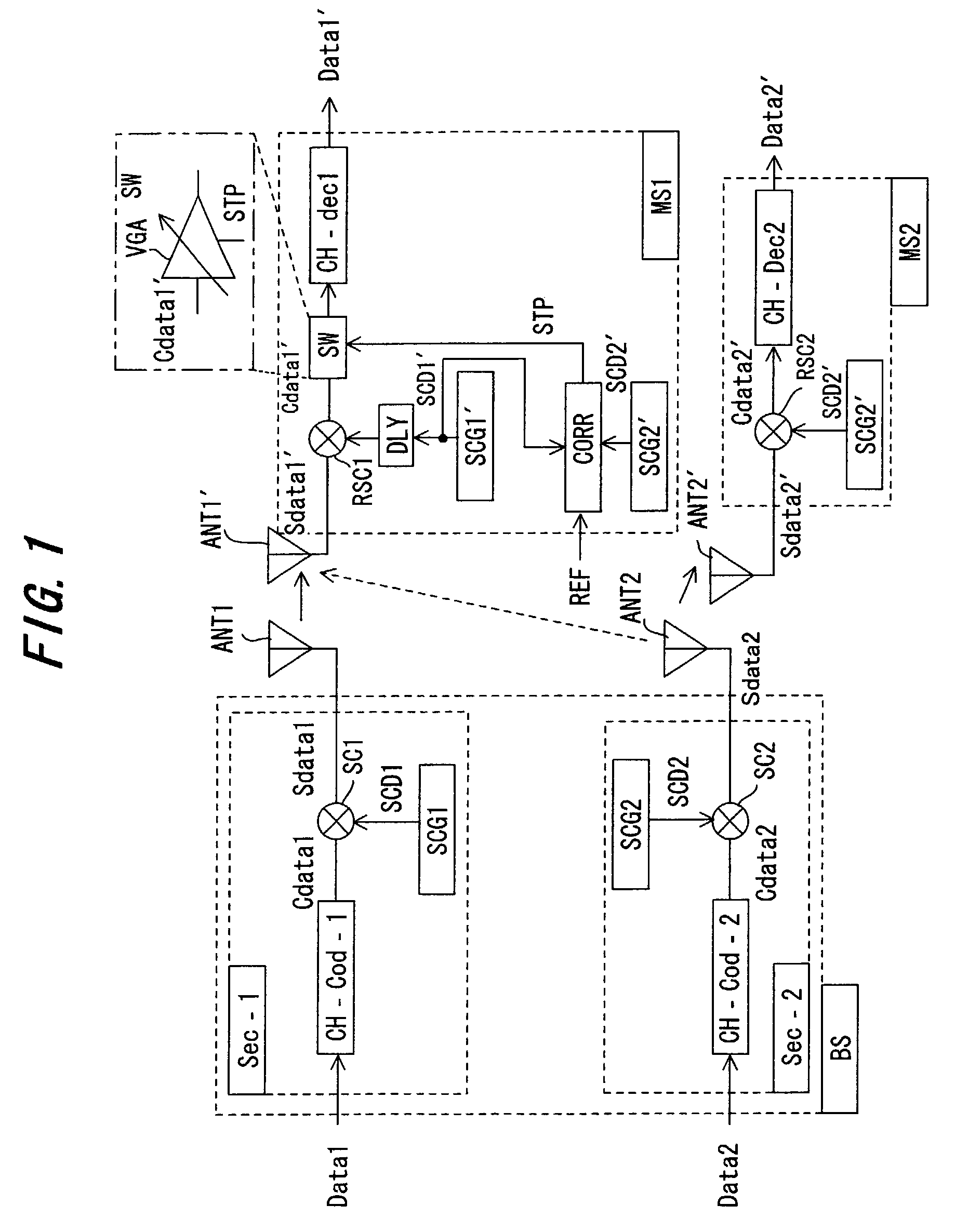
[0043]FIG. 1 is a block diagram of a code division multiple access communication system that includes a code division multiple access signal receiver according to the present invention. This illustrates a case in which a cell has been divided into sectors. Further, the Figure illustrates an example of a case where user data signals Data1, Data2 are transmitted from a single base station (transmitting apparatus) BS to mobile stations (receiving apparatus) MS1, MS2 in two sectors neighboring each other.

[0044]Sectors Sec1, Sec2 in the base station BS have transceive antennas ANT1, ANT2 possessing separate directivities and, by virtue of the antenna directivities, take charge of the sending and receiving of signals to and from coverage areas (sectors) that are geographically independent of each other. Portions of the base station BS and mobile stations MS1, MS2 in FIG. 1 that have no bearing upon the present invention are deleted, although the deleted structure...

first modification

[0051

[0052]In the above embodiment, control for halting passage of a receive signal is carried out only by the mobile station MS1. Depending upon a change in the reception environment, however, the mobile station MS2 also may exercise control for halting passage of a receive signal as appropriate. Further, the foregoing is described with regard to a single combination of spreading-code sequences, in which the spreading-code sequences used in respective ones of the mutually adjacent sectors are SCD1, SCD2. In actuality, however, there are multiple combinations of spreading-code sequences and the above-described control is performed with regard to the appropriate combinations. In addition, though the foregoing is for a case that takes into consideration spreading-code sequences used in mutually adjacent sectors, the above-described control can be applied to spreading-code sequences used by mutually adjacent base stations.

second modification

[0053

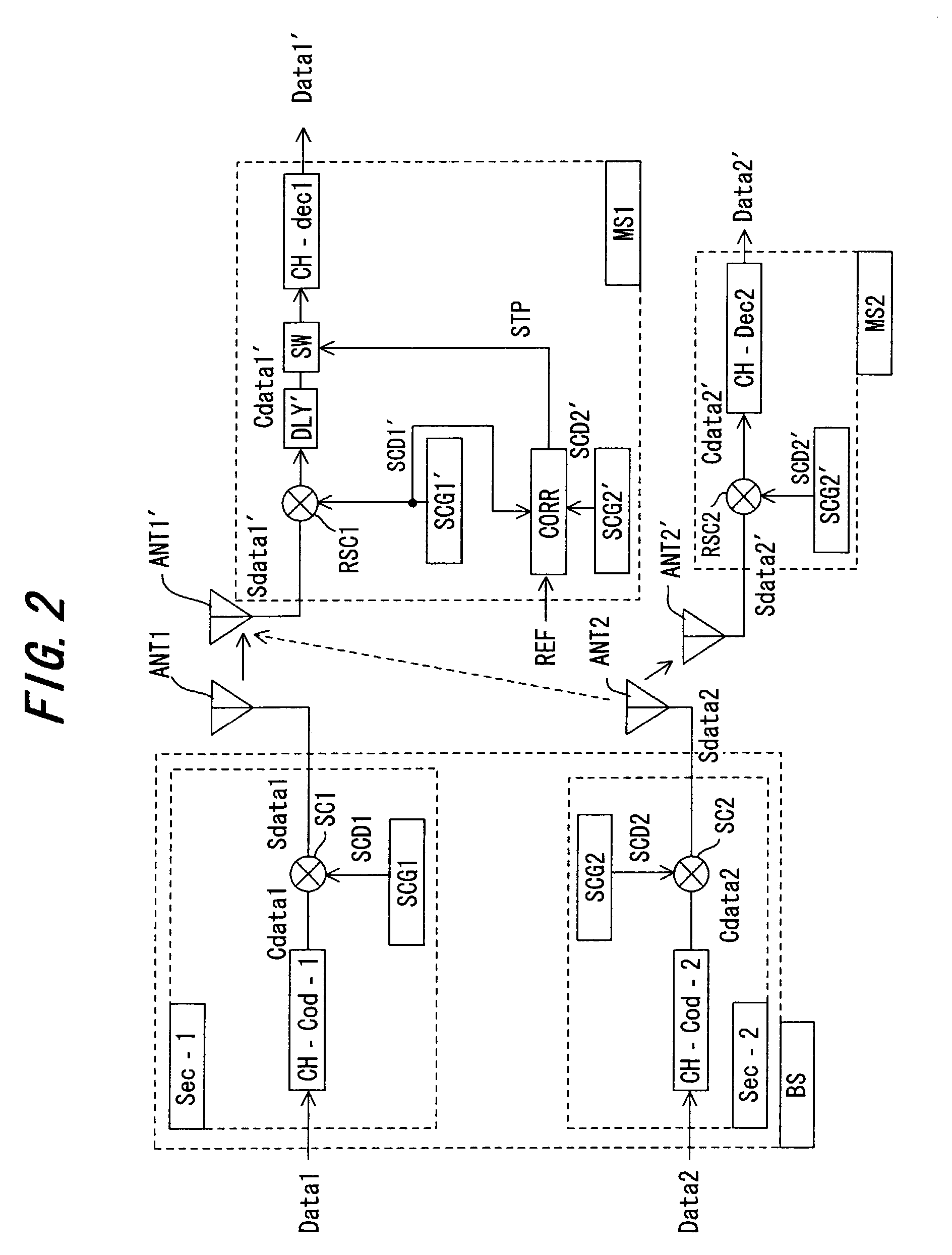
[0054]FIG. 2 is a modification of the first embodiment, in which components identical with those of the first embodiment are designated by like reference characters. The difference is the location of the delay unit. Specifically, in the first embodiment, the despreading-code sequence SCD1′ is delayed a prescribed period of time. In the modification, however, the despread signal Cdata1′ output from the despreading circuit RSC1 is delayed a prescribed period of time. That is, a delay unit DLY′ in this modification delays the despread signal Cdata1′ for a predetermined period of time in such a manner that the despread signal Cdata1′ will enter the switch SW following the completion of calculation of the cross-correlation value.

[0055]Structure of Cross-correlation Detector

[0056]FIG. 3 is a block diagram of the cross-correlation detection controller, and FIG. 4 is a diagram useful in describing the operation thereof. This illustrates a case where partial correlation of despreading-c...


PUM


Abstract

In a code division multiple access signal receiving apparatus for demodulating transmit data by subjecting a receive signal to despread processing using a code sequence identical with a spreading-code sequence on a transmitting side, a cross-correlation detector calculates a cross-correlation value, on a per-symbol basis, between a spreading-code sequence for spread-spectrum modulating local-station-addressed transmit data and a spreading-code sequence for spread-spectrum modulating other-station-addressed transmit data; a discriminator discriminates whether the calculated cross-correlation value has exceeded a threshold value; and a switch halts input, to a decoder, of a portion of the receive signal that corresponds to the full interval or partial interval of a symbol where the cross-correlation value exceeds the threshold value.

Description

[0001]This application is a continuation of international application number PCTJP00 / 04607, filed Jul. 11, 2000.BACKGROUND OF THE INVENTION[0002]This invention relates to a code division multiple access signal receiving apparatus and, more particularly, to a code division multiple access signal receiving apparatus, which is for receiving a spread-spectrum modulated signal and reproducing transmit data, in a code division multiple access communication system.[0003]In a CDMA (Code Division Multiple Access) mobile communications system, a base station spread-spectrum modulates control information and user information of each user by employing different spreading code sequences, multiplexes the modulated information and transmits the same. Each mobile station in the system sends and receives information upon spreading and despreading the information using a spreading code sequence specified by the base station.[0004]FIG. 16 is a block diagram of a CDMA transmitter in a base station that...

Claims


Application Information

Patent Timeline
Patent Type & Authority Patents(United States)
IPC IPC(8): H04B1/707H04J13/00H04B1/7103H04B7/04
CPCH04B1/707H04B1/7103H04B7/0491
Inventor NAKAMURA, TAKAHARU
Owner FUJITSU LTD
Learn More